10
MULTIPORT ELECTRONIC CONTROLLER continued...
Any time during the movement of the valve, whether by remote commands in REMOTE
mode, or by the STEP/JOG pushbutton in STEP mode, or by the HOME button on the
circuit board, the valve can be stopped by switching the selector switch to JOG mode on the
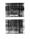
control station. In normal operation, the circuit board (MP-08) will be displaying a flashing
RUN LED to indicate the microcontroller is running normally, similar to the flashing decimal
point on the optional digital display. The circuit board also has a MOTOR RUN LED which
will turn on while the motor is running.
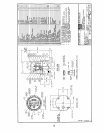
The position of the valve plug is shown by the indicator and the indicator plate on top of the
Multiport Selector Valve. The optional digital display shows the port number which where
the valve is at, or near. See details in section for "OPTIONS".
CAUTION: Since the valve can be controlled remotely, make sure power is disconnected
from the entire unit if maintenance is being done on the valve.
H. HOME PORT (POSITION #8) CALIBRATION
CAUTION: Always ground yourself before touching the switch to prevent static discharge.
To calibrate the Multiport Valve to a home port position, remove the top cover to expose the
controller circuit board (MP-08). Use the JOG button on the circuit board to position the
valve plug exactly to the selected home port position.
NOTE: Very brief momentary contact is required for small movements of the valve plug.
It is recommended that the home port blind flange be removed and the plug
position in the valve body be checked visually.
If the optional control station is connected, the valve can be positioned by switching to JOG
mode and pressing the STEP/JOG pushbutton.
NOTE: The correct alignment of the plug seal to the port can be visually checked by
lining up the hex corner of the lower connector with the applicable slot on the
indicator plate.
In the middle of the circuit board there is a small pushbutton marked "SET ZERO". Press
and hold the "SET ZERO" button for 10 seconds and release. If the digital display option is
installed, it will display #0 when the "SET ZERO" button is pressed for 10 seconds, but
change to #8 when calibrated. As well, the RUN LED will flash rapidly for 10 seconds, until
calibration is complete.
The present valve home port position is now calibrated and will be stored in the controller's
memory as position #8. If the optional digital display is connected, the display will first show
'0' when the SET ZERO button is depressed, and then change to show '8' to indicate for
position #8. Further movements of the valve will be referenced to the home port. When
viewed from above, the Multiport Valve rotates counter-clockwise (CCW) only, the first port
CCW relative to the home port (#8) will be position #1. Note that the home position can be
configured with a portable computer to be any port position on the Multiport Valve. The
home port position is stored in EEPROM memory.
NOTE: The factory default home port is always set to #8. If the home port is set to any
other port position (from #1 to #7), then the first port CCW relative to home port in
this case will be the next higher #port (ie. if home is #7, then next port relative to
home is #8).


