


11
MULTIPORT ELECTRONIC CONTROLLER continued...
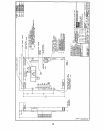
I. DISABLING PORT POSITIONS
CAUTION: Always ground yourself before and while touching the jumpers to prevent
static discharge.
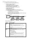
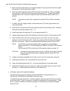
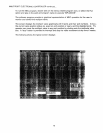
A set of 8 jumper pins near the top right of the circuit board marked "DISABLE PORT" are to
allow the installer to disable certain positions of the valve. Installing a shorting plug
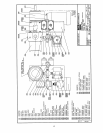
between the two pins will disable the specified position. Refer to board drawing on page 18
for jumper location. The positions are marked '1' to '8' on the circuit board. When
advancing in manual STEP mode with the optional control station, the controller will skip
over the disabled position and continue to advance to the next enabled position.
NOTE: When a position is disabled, the controller will not accept a command to go to that
position. The controller will just respond to the command with a 'disable' status.
Using remote RS-485 communication, if a disabled port is selected the MEC
controller will not move to that position.
J. CONTROLLER ADDRESS
CAUTION: Always ground yourself before and while touching the jumpers to prevent
static discharge.
A set of 8 jumper pins near the top left of the circuit board marked "ADDRESS PORT" are
to allow the user to set a unique address for the MEC controller. With power supply off,
setting a jumper across the two pins will set the controller to the specific address (in
decimal). The user can select single or multiple jumpers, the address (in decimal) will be
the sum of all jumpers that have been set (ie. if all 8 jumpers are set, then the controller
address is [1+2+4+8+16+32+64+128] = 255). When power supply is restored, the address
will be set. Refer to MP-08 board drawing on page 18 for the jumpers location.
NOTE: Communication error will occur when two different MEC controllers are set to the
same address.
When operating the MEC controller with the optional MEC software program, the address
jumper '1' must be set.
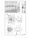
K. CONTROLLER ASSEMBLY
NOTE : See the typical MEC assembly drawing on page 15.
1. Install two retaining rings (10) into the grooves on shaft (6). Lubricate two washers (9)
and insert a washer (9) over each end of shaft (6) and rest on the retaining rings (10).
Engage setscrew (8) to shaft (6). Lubricate and install o-ring (7) on shaft (6).
2. Lubricate the center bore of housing (1). Insert the shaft (6) assembly into housing (1)
from the top bevelled end.
3. Attach solid state relay (18) to lower bracket (12) using screws (19). Install guide pin
(16) to lower bracket (12) using nut (17).
4. Install two posts (11) in housing (1). Loosely attach the lower bracket (12) assembly
over shaft (6) onto the posts (11) using capscrews (13), washers (14) and lockwashers
(15).