


3
ACTUATOR ASSEMBLY continued . . .
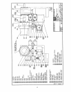
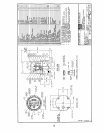
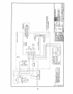
5. See the typical drawing for Switchpak SW20N assembly on page 15, and the typical
wiring diagrams on page 16 for DC supply and page 17 for AC supply. Install all wiring
according to the electrical diagram and local regulations.
6. Check shaft alignment of the electronic controller to speed reducer by rotating both
shafts independently, without binding occurring in the connector. Adjust if necessary.
7. With the Switchpak, the optional local control station and/or the digital display aligned on
the Switchpak pedestal, tighten all mounting bolts, nuts and setscrews.
8. Pour seal enclosure (315), or tag.
9. Tag power supply connection wires in enclosure (334), install plug (303) and tag as
power supply field connection point.
10. Install entry plugs (301, 302, 309) in the Switchpak SW20N enclosure (300) and tag as
communication field connection point.