


MULTIPORT ELECTRONIC CONTROLLER continued...
7
2. MODBUS RTU PROTOCOL/RS-485 CONNECTION
• Modbus RTU mode communications
• Supports unit address 1 to 250
• Two wire RS-485 or five wire RS-232 operation
• Allows 32 MECs network on a communication line
• 9600 baud, 8 data bits, 1 stop bit, no parity
• Uses 120 OHMS 24 AWG twisted pair shielded cable
• Cable example: Belden #9841
• Multidrop configuration
• 4000 feet maximum cable length
• 120 OHMS termination resistor required at the furthest point
• Control board (MP-08) interface uses Linear Technology LTC-485 I.C.
- 70 mV Hysteresis
- -7 Volts to 12 Volts Common Mode Range
- Auto thermo shutdown in case of cable short
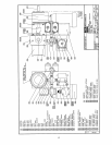
- Set address ports as required, and jumper 'B' for RS-485. Refer to board
drawing on page 18 for these jumper locations.
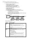
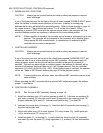
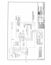
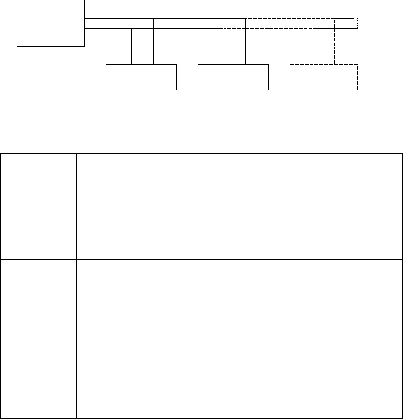
RS-485 network diagram
HOST
DEVICE
(COMPUTER/PLC)
RS-485 120 OHM TWISTED PAIR SHIELDED CABLE
120 OHM
TERMINATING
RESISTOR
BETTIS MEC
ADDRESS PORT 1
BETTIS MEC
ADDRESS PORT 2
UP TO 32 TOTAL
BETTIS MEC
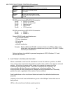
Modbus register definitions
Function 3 Read data from register
Function 6 Write data to register
Register
40001
Write to set Position.
- Setting bits 1 to 8 in this register will move the valve to required
position.
- The bit will be cleared when the position is made.
- If controller is not in REMOTE mode, the motor will not start and the
bit
will be cleared.
- Setting bit 16 while the motor is running will stop the motor
immediately.
Register
40002
Read current position and status.
- Bits 1 to 8 will indicate the position the valve is near (1 = Near or On
Position.)
- Bit 9 set in JOG mode.
- Bit 10 set in STEP mode.
- Bit 11 set in REMOTE mode.
- Bit 12 indicates motor running.
- Bit 13 indicates motor running but no movement (equipment failure.)
- Bit 14 set indicates motor running but cannot find exact valve
location
(equipment failure).
- Bit 16 set will indicate that the valve is exactly on position with bit 1
to 8
indicating position. If bit 16 is not set the valve is near a position.