


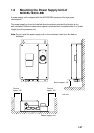

1-23
Using inside fixing holes of the antenna housing
This method requires removal of the RF unit in the antenna unit to access inside fixing
holes. Use hex head bolts, flat washers, spring washers and nuts (local supply) to mount
the antenna unit, confirming length of bolts.
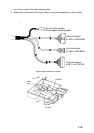
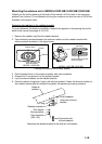
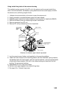
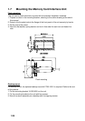
1. Unfasten four scanner bolts on the cover to open the antenna unit.
2. Unplug connector connected between upper and lower chassis.
3. Separate upper chassis from lower chassis by removing two hex head bolts (M8x25).
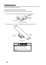
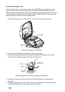
4. Remove the board cover by unfastening four pan head screws.
5. Remove connector from RF unit.
6. Remove RF unit by unfastening four hex head bolts.
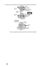
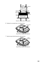
RFunit
Hex head bolt
M10X20 4 pcs.
Hex head bolt
M8X25
2 pcs.
Spring Washer
M10 4 pcs.
Board cover
Pan head screw
M3X8 4 pcs.
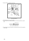
Upper chassis
Square bushing
Lower chassis
Antenna unit chassis, upper chassis separated
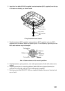
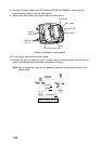
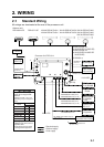
7. Lay the corrosion-proof rubber mat (supplied) on the mounting platform.
8. Fasten the lower chassis to the mounting platform with hex head bolts, spring washers,
flat washers and nuts (local supply), and then coat flat washers, nuts and exposed parts
of bolts with silicone sealant. Cut a slit in the rubber bushing and insert bolt into the
bushing. Do not use seal washers.
9. Reassemble RF unit, cover and chassis.
10. Set four knob caps (supplied) into outside fixing holes.
11. Do steps 6-8 in “Outside fixing holes”.