


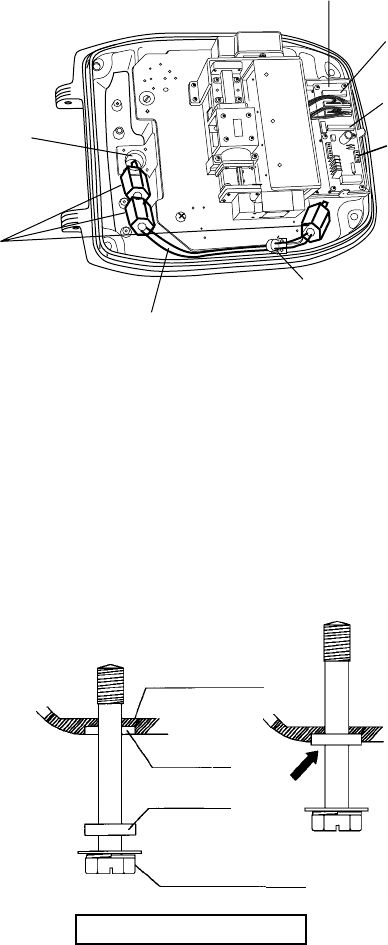
1-26
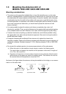
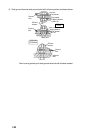
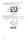
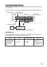
8. Connect the signal cable to the RTB Board (03P9249 or 03P9250), referring to the
interconnection diagram and the figure below.
9. Attach three EMI cores to the signal cable as shown below.
Route cable along here.
Lead in
cable here.
J821 VH9P
RTB Board
J824 NH13P
J823 VH4P
EMI core
RFC-13
Clamp
Antenna unit chassis, cover opened
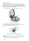
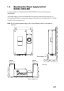
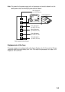
10. Fix the signal cable with the cable clamp.
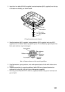
11. Release the stay and close the cover. Loosely fasten the scanner bolts; you will have to
make some adjustments inside after completion of wiring.
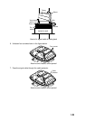
Note: When closing the cover, set the gaskets to grooves in the bottom chassis, then
tighten bolts.
BOTTOM
CHASSIS
GASKET
GROOVE
SCANNER BOLT
Torque : 9.8 ±0.1 N m
.