


v
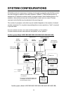
SYSTEM CONFIGURATIONS
All NavNet products incorporate a "network circuit board" to integrate each NavNet product
on board through an optional LAN cable (Ethernet 10BASE-T). Each NavNet product is
assigned an IP address to enable transfer of images between other NavNet products. For
example, video plotter pictures can be transferred to a radar and vice versa. Pictures
received via the NavNet may be adjusted at the receiving end.
The number of processor units which may be installed depends on the number of network
sounder connected. For a system incorporating three or more products, a "hub" is required
to process data.
For one network sounder: one radar and three plotters, or four plotters
For two network sounder: one radar and two plotters, or four plotters
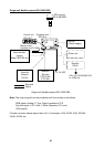
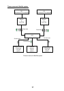
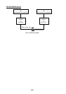
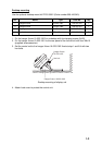
NavNet system (Model 1823C-BB/1833C-BB/1933C-BB/1943C-BB/1953C-BB)
Heading
sensor
Plotter, etc.
Rectifier
RU-3423
GPS receiver
GP-310B/320B
12 - 24 VDC*
Network
Sounder
ETR-6/10N
ETR-30N
Other NavNet
system
(GD-1900C-BB etc.)
Antenna Unit
MODEL
1833C-BB
MODEL
1933C-BB
MODEL
1943C-BB
Processor unit
RPU-014
100/110/115/220/230 VAC
1φ, 50/60 Hz*
monitor
(Owner supply)
(See next page)
MODEL
1953C-BB
Control unit
RCU-017
Power Supply
Unit PSU-005
*: The power for the power supply unit
and display unit must be drawn from
the same power source.
Facsimile
Receiver
FAX-30
MODEL1823C-BB
PUSH TO ENTERPUSH TO ENTER
DEFDEF
MNOMNO
VWXVWX
_'#_'#
POWERPOWER
RANGERANGE
TXTX
00
JKLJKL
44
77
STUSTU
55
88
ABCABC
2211
BB
GAINGAIN
ALARMALARM
EBLEBL
VRMVRM
PQRPQR
YZ&YZ&
66
99
DISPDISP
EE
MENUMENU
CC
DD
CLEARCLEAR
GHIGHI
33
SAVESAVE
MOBMOB
HIDEHIDE
SHOWSHOW
AA
POWER
DATA 3
NETWORK
CONT DATA 1DATA 2
DJ-1
SLAVE DISPLAY
RGB OUT
NTSC/PAL
2
GND
3
INPUT
12-24 VDC
1
CARD SLOT
3
2
1
GND
F.G.
12 VDC
OUTPUT
OPTION
: Option
:Standard
Memory card
interface unit CU-200
NavNet system (Model 1823C-BB/1833C-BB/1933C-BB/1943C-BB/1953C-BB)