


www.furuno.co.jp
All brand and product names are trademarks, registered trademarks or service marks of their respective holders.
MARINE RADAR/ARPA
FAR-2827W/2837SW
Installation Manual Comply with MSC.192(79)
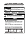
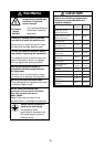
SAFETY INSTRUCTIONS....................... i
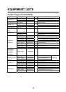
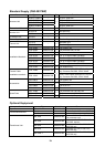
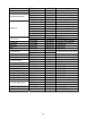
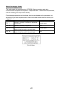
EQUIPMENT LISTS .............................. iii
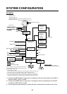
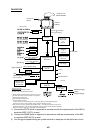
SYSTEM CONFIGURATION ................. vi
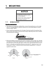
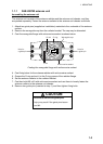
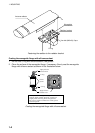
1. MOUNTING ..................................... 1-1
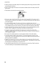
1.1 Antenna Unit .........................................1-1
1.2 Monitor Unit.........................................1-12
1.3 Control Unit .........................................1-16
1.4 Processor Unit ....................................1-21
1.5 Transceiver Unit ..................................1-22
1.6 Power Supply Unit ..............................1-23
2. WIRING ........................................... 2-1
2.1 Interconnection .....................................2-1
2.2 Antenna Unit .........................................2-3
2.3 Transceiver Unit ..................................2-12
2.4 Monitor Unit.........................................2-23
2.5 Processor Unit ....................................2-24
2.6 Changing AC Power Specification of
Processor Unit ...................................2-29
2.7 Power Supply Unit ..............................2-30
3. SETTING AND ADJUSTMENT ....... 3-1
3.1 DIP Switch Setting ................................3-1
3.2 Initializing Tuning ..................................3-2
3.3 Heading Alignment ............................... 3-3
3.4 Adjusting Sweep Timing ....................... 3-6
3.5 Suppressing Main Bang ....................... 3-7
3.6 Other Settings ...................................... 3-8
3.7 Dual Radar Display (non IMO-type only) .
...................................................... 3-16
4. INSTALLING OPTIONAL
EQUIPMENT........................................4-1
4.1 Gyro Converter GC-10 ......................... 4-1
4.2 Memory Card Interface Unit ................. 4-9
4.3 DVI-RGB Conversion Kit (for VDR
connection)........................................ 4-12
4.4 BNC Connector Converter ................. 4-15
4.5 Junction Box RJB-001........................ 4-16
5. INPUT/OUTPUT DATA ....................5-1
INSTALLATION MATERIALS,
ACCESSORIES, SPARE PARTS ....... A-1
OUTLINE DRAWINGS ....................... D-1
INTERCONNECTION DIAGRAMS..... S-1
Back