


vi
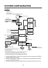
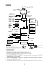
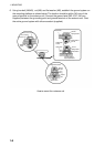
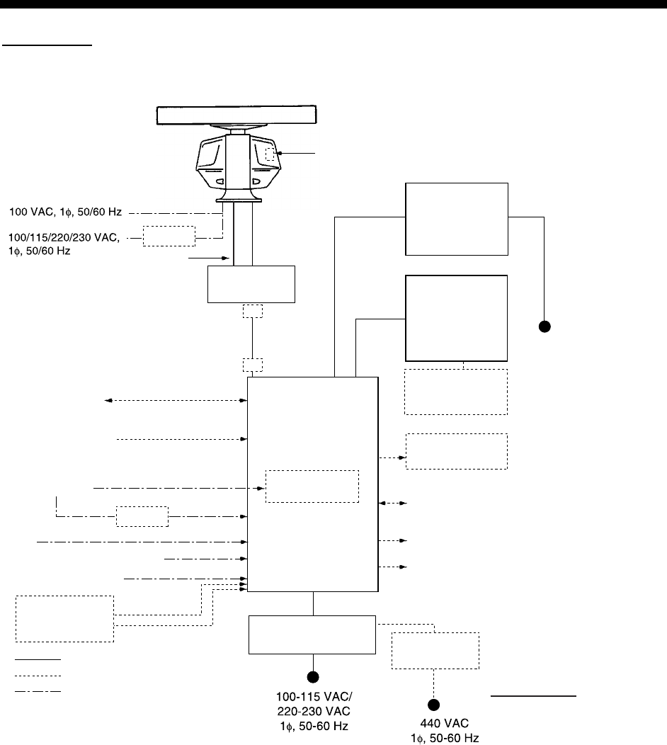
SYSTEM CONFIGURATION
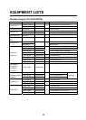
FAR-2827W
Processor Unit
RPU-013
Navigator
IEC-61162-1 Serial Data*
2
(Input/Output)
IEC-61162-1 Serial Data
(Input)
Speed Log
Gyro Compass
AIS
Switching HUB HUB-100
Track Control Unit
: Option
: Dockyard supply
: Standard
AD-100
Memory Card
Interface Unit
CU-200-FAR
VDR
External Monitor
Sub Display
Alarm
*
4
Monitor Unit
MU-231CR
or
MU-231
Control Unit
RCU-014
(Standard)
or
RCU-015
(Trackball)
Control Unit
RCU-016
(Remote)
XN20AF-RSB-103
XN24AF-RSB-103
Antenna Unit
Gyro Converter
GC-10
Performance Monitor
RJB-001*
1
100-230 VAC
Transceiver unit
RTR-081A
Waveguide
WRJ-9 or FR-9
RU-3305
RJB-001*
1
Category of Units
Antenna unit: Exposed to weather
All other units: Protected from weather
Step or synchro signal
IEC-61162-2
*
1
When length of antenna cable is more than 100 m.
*
2
For IMO spec, IEC-61162-1 Edition 2 is required.
*
3
Russian flag vessels only.
*
4
Contact output for Alarm
(Load current) 120 mA, (Polarity) No.1/2: Normally Close, No.3/4: Normally Open
Serial I/O for alarm is also possible, which complies with IEC 61162-1.
(For de-icer)
Transformer Unit
RU-1803
Power Supply Unit*
3
PSU-011
1)
2)
3)
*
5
This monitor has been approved by the IMO (CAT1). If a different monitor is to
be used, its effective diameter must meet the applicable Category requirements
(effective diameter 320 mm or higher). Refer to its operator's manual for details.
*
5
1) Connect the EPFS which is approved in accordance with the requirements of the IMO in
resolution MSC.112(73) is used.
2) Connect the SDME which is approved in accordance with the requirements of the IMO
in resolution MSC.96(72) is used.
3) Use the gyrocompass having an update rate that is adequate for the ship’s rate of turn.