


2. RADAR, CHART RADAR OPERATION
2-51
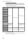
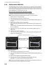
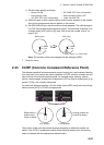
1) Set the radar settings as follows:
2) Adjust the gain so that a slight amount of white noise appears on the screen.
Arcs for the performance monitor appear on the screen.
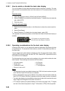
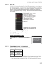
3) Set [PM GAIN ADJ] so that the outer arc faintly appears. The setting range is
0 to 255. Wait at least eight scans then adjust. The following illustration is an
example when [ARC] is set to [5] (see "How to set the number of arcs" on
page 2-49).
Note: The location of the arcs changes with the setting of [ARC].
7. Close the menu.
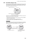
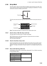
2.33 CCRP (Common Consistent Reference Point)
The reference position for measurements (range, bearing, etc.) and markers (heading
line, stern mark, etc.) can be the antenna position or CCRP, which is a location on own
ship to which all horizontal measurements, for example range, bearing, relative
course, relative speed, closest point of approach (CPA) or time to closest point of ap-
proach (TCPA), are normally referenced.
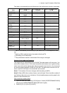
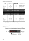
To select the reference position, click the button below [REF point] at the top-left po-
sition to select [ANT] or [CCRP] as appropriate.
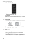
The position of the own ship marker changes according to reference position as
above. If the CCRP is positioned outside of the effective display area, the bearing
scale is indicated with the appropriate reduced detail.
• Range: 24 NM • A/C RAIN: OFF (turn off manually)
• Pulse Length: Long • Echo Averaging (EAV): OFF
• A/C SEA: OFF (turn off manually) • Video Contrast: 2-B
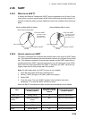
Before setup
Before setup
After setup
After setup
Approx. 12.1 NM (10 dB)
8.1 NM to
10.1 NM
8.1 NM to
10.1 NM
Click button to switch
Conning position set
at center of display
Radar antenna
position set at
center of display
ANT position
CCRP position