


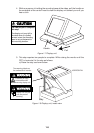

1-14
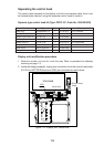
Wiring between display unit and control head
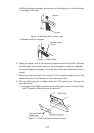
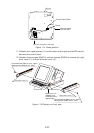
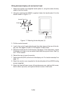
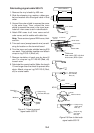
1. Fasten the handle to the supplied handle plate (V), using the screws formerly
used to fixed the handle.
2. Using two upset screws (M5X10, supplied), fasten the handle plate (V) to the
location shown in Figure 1-17.
Insert handle
plate (V) here.
Handle Plate (V)
DOWN
Upset Screw
2 pcs.
Handle
Figure 1-17 Attaching the handle plate (V)
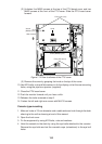
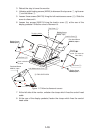
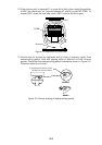
3. Pull the monitor forward.
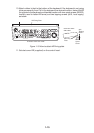
4. Lead in the control head cable through the cable clamp at the rear of the dis-
play unit. See pages 2-9 and 2-10 for location of cable clamp.
5. Raise the monitor and fix it with the stay. (See page 1-5 for instructions.) Inside
the display unit, plug in two connectors and fasten two ground wires. See Fig-
ure 1-12 for location.
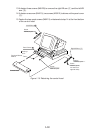
6. Retract the stay to lower the monitor.
7. Fasten two bolts (M10) at the front of the display unit. For location see step 3 on
page 1-5.
8. Attach the monitor cover (supplied) to the handle plate with two M4X8 binding
screws (supplied).
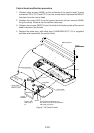
9. Attach right and left lower covers, left maintenance cover, right and left covers,
lead-in cover, top cover, and right and left arm covers in that order.