


4-11
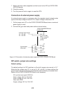
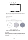
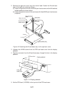
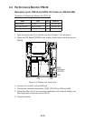
2. Remove the right arm cover from the control head. Fasten the M-card base
assy. to the right arm cover as follows:
a) Fasten the ground wire with the M4X8 pan-head screw and the M4 teethed
locked washer as shown below.
b) Fasten the right arm cover to the card case with three M4X8 pan-head screws
(supplied).
Right arm cover
Pan-head screw
M4X8
Pan-head screw
M4X8 (3 pcs.)
Toothed lock
washer M4
M-card base assy.
Ground wire
Card slot
FRONT
Figure 4-9 Fastening the M-card base assy. to the right arm cover
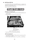
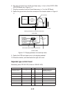
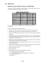
3. Unfasten four M4X8 screws from the PCB card case cover from the display
pedestal.
4. Pass the connector from the M-card base assy. through the hole in the display
pedestal.
Display pedestal
PCB card
case cover
PCB card slot
Figure 4-10 Display pedestal
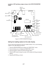
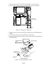
5. Set the RP Board (14P0298) in the top slot of the PCB card case.