


AP-2
DATA SHEET 1
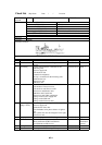
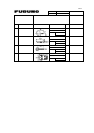
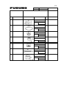
General check
CK; DT: digital tester AT: analog tester OS:oscilloscope WC:watch
Check item Content Check point CK Standard Judge
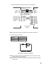
Connection All connection
should be checked
refering to the
interconnection
diagram.
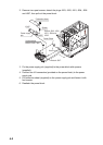
1.Transducer-transceiver unit
2.Processor unit-Transceiver unit
3.Processor unit-Control unit
4.Processor unit-Others equipment
5.Ship’s mains-Power supply
unit-Processor unit
WC
Refer to
installation
manual
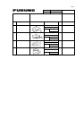
Grounding All grounding
should be checked
by installation
manual.
1.Monitor unit
2.Processor unit
3.Transceiver unit
4.Power supply unit
5.Junction box(Option)
WC
Refer to
installation
manual
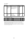
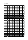
Power Supply(ship’s main voltage)
Unit Check point CK Standard Result Judge
Processor unit CN-A110 DT
AC100/110/115/220/230V±10%
Transceiver unit TB-B101 #1---#2 DT AC90V to AC115V
Power supply unit TB-D102 DT
AC100/110/115/220/230V±10%
Hull unit TB-C101 DT AC220V
Note that: The input voltage may be dropped while the capacitors are being charged before
transmission. For accurate data, please check the voltages during TX on and off as well when you
check the input voltage of a transceiver unit.
The input voltage monitoring circuit in transceiver unit detects low voltage when AC 100V power
source drops to 85V. On the other hand, if the input voltage is 120 to 130V, the over voltage flag is
set and an alarm is displayed to monitor.