


2
InstallatIon
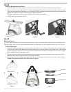
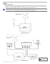
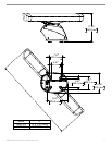
Installing the Scanner
The following section covers the assembly and installation of the GMR 404 or GMR 406 marine radar. The GMR 404 and 406 only operate
with components of the Garmin Marine Network, and MFDs (multifunction displays). See your Garmin dealer or the Garmin Web site for more
details. To complete the installation, you need the appropriate fasteners, tools, and mounts. These items should be available at most marine
dealers. Always wear safety goggles, ear protection, and a dust mask when drilling, cutting, or sanding. When drilling or cutting, always check
rst to see what is on the other side of the surface. If you experience difculty with the installation, contact Garmin Product Support or seek the
assistance of a professional installer.
WARNING: The selected radar mounting location must be able to hold the weight of the radar and any inertial forces.
Installation Guidelines
To maximize the performance of the radar, please observe the following installation guidelines:
• An ideal scanner mounting location is high above the ship’s keel line with a minimal part of the vessel’s structure or rigging blocking
the radar beam. Obstructions in the path of the radar beam may cause blind and shadow sectors, or generate false echoes. The higher the
installation position, the further the scanner can detect targets.
• Avoid mounting the scanner on the same level as smoke stacks, horizontal spreaders, or crosstrees on a mast. Do not install the scanner
near heat sources where it may be subjected to smoke or hot air from smoke stacks or heat from lights.
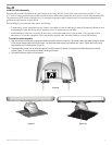
• The mounting surface or platform should be sturdy enough to support the weight of the radar and any inertial forces, at as possible, and
parallel with the vessel’s water line.
• It is recommended that the scanner be mounted out of range of personnel (horizontal beam width above head height). When the scanner is
transmitting, do not look directly at the antenna at close range, because the eyes are the most sensitive part of the body to electromagnetic
energy. When properly installed and operated, the use of this radar conforms to the requirements of ANSI/IEEE C95.1-1992 Standard for
Safety Levels with Respect to Human Exposure to Radio Frequency Electromagnetic Fields.
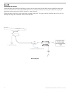
• A “Compass Safe Distance” must be maintained between the compass and the scanner. The Compass Safe Distance is measured from the
center point of the compass to the nearest point on the scanner.
Standard compass = 3.28 ft (1 m)
Standby Steering and Emergency compasses = 1.97 ft (0.6 m)
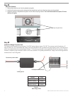
• Mount other electronics and cables more than 7 ft (2 m) from the path of a radar beam. A radar beam can normally be assumed to spread
25° vertically above and below the scanner’s radiating element. For vessels with higher bow angles at cruise speed, it may be helpful to
lower the angle so the beam points slightly downward to the waterline while at rest. Shims may be used as necessary.
• Install the scanner away from antennas or other electronics. GPS antennas should be either above or below the radar beam path of the
scanner. Mount at least 3 ft (1 m) from any equipment transmitting or cables carrying radio signals, such as VHF radios, cables and
antennas. In the case of SSB radios, the distance should be increased to 7 ft (2 m). IEC 60936-1 clause 3-27.1 states maximum distances
from the antenna at which RF (radio frequency) levels can be expected.
GMR 404 (100W/m squared = 60" [151 cm]) (10W/m squared = 187" [475 cm])
GMR 406 (100W/m squared = 75" [189 cm]) (10W/m squared = 236" [598 cm])
• The scanner transmits electromagnetic energy. It is important that the radar is turned off or the DC power input is disconnected when
personnel are required to come close to the scanner to perform work on the scanner assembly or associated equipment.
GMR 404/406 Radar Installation Manual