


4
GMR 404/406 Marine Radar Installation Instructions
Step
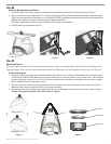
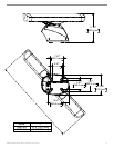
Mount the Antenna:
1. Remove the protective cover from the pedestal wave guide.
2. Verify that the antenna wave guide is aligned with the pedestal wave guide and slide the antenna onto the pedestal.
3. Secure the antenna to the pedestal using the 8 mm hex bolts and spring washers. The 8 mm bolts should be torqued to 70 in.lbs
(6 ft.lbs) (.81 kgf.m).
align waveguide faces
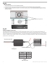
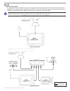
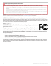
15 Amp Slow Blow Fuse
To scanner power cable
Figure 7
Wire Gauge Table
Distance Gauge
3 meters (9.8 ft) 12 AWG
5 meters (16.4 ft) 10 AWG
6.5 meters (21.3 ft) 9 AWG
8 meters (26.2 ft) 8 AWG
To RF ground
To ship’s power
Step
Install the Voltage Converter Unit
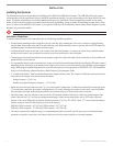
The voltage converter requires an input voltage of 10-40VDC and provides an output of 36 VDC. The converter must be fused using a 15
Amp slow-blow fuse. It is recommended that voltage converter be installed as close as possible to the selected power source. If the input wires
need to be extended, follow the recommendations in Figure 7. If the wires are extended, use the supplied heat shrink butt connectors. After the
connector is crimped, heat the connector to shrink it for a water resistant t. For optimal performance, the voltage converter housing should be
connected to the vessel’s RF ground.