


12 GPSMAP 4000/5000 Series Installation Instructions
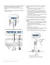
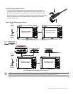
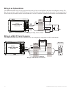
Wiring to an Optional Alarm
The GPSMAP 4000/5000 series unit can be used with a lamp, a horn, or both, to sound or ash an alert when the unit displays a message. The
alarm does not need to be wired for the 4000/5000 unit to function. The alarm circuit pulls low when the alarm sounds. The maximum current is
100 mA, and a relay is needed to limit the current from the unit to 100 mA. A switch can be installed to select between visual and audible alerts.
Wiring to a lamp, a horn, or both.
+
-
Garmin
GPSMAP 4000/5000
Series Unit
WIRE
COLOR
RED (POWER)
BLACK (GND)
YELLOW (ALARM)
BATTERY
10-35 VDC
RELAY
100 mA MAX
COIL CURRENT
HORN
LAMP
FUSE
7.5A - 42V
POWER
CABLE
NMEA 0183
CABLE
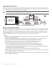
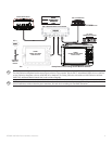
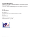
Wiring to a DB-9 PC Serial Connector
The GPSMAP 4000/5000 series unit can be connected to a PC with a serial port by wiring the unit to a DB-9 serial connector.
Wiring to a DB-9 Serial PC Connector
+
-
>
>
>
>
>
>
1
4
6
7
8
9
2
3
5
Garmin
GPSMAP 4000/5000
Series Unit
DB-9 Serial
PC Connector
BATTERY
10-35 VDC
WIRE
SEE TABLE FOR
WIRE COLORS
DB-9 PIN
NUMBERS
RED (POWER)
BLACK (PWR GND)
FUSE
7.5A - 42V
BLACK (DATA GND)
RX / B(-)
RX / A(+)
PIN 5: GND
PIN 3: TX
POWER
CABLE
NMEA 0183
CABLE
UNCONNECTED
PIN 2: RX
TX / B(+)
TX / A(-)
End View