


16 GPSMAP 6000/7000 Series Installation Instructions
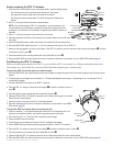
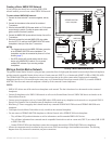
The GPSMAP 6000/7000 series chartplotters allow video input and monitor output using the included marine video 17-pin cable. The
GPSMAP 7015/7215 chartplotters have a second marine video 17-pin cable to allow for additional video sources. The GPSMAP 6000/7000
series chartplotters allow for National Television System Committee (NTSC) and Phase Alternate Line (PAL) composite video sources, and PC
monitor output (6008/6208 = VGA output, 6012/6212/7012/7212/7015/7215 = XGA output). The marine video cable inputs are only available
on the chartplotter to which they are attached and will not transmit over the Garmin Marine Network. For detailed marine video pinout
information, see the appendix (page 19).
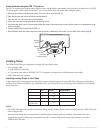
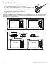
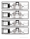
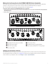
This cable is supplied with all GPSMAP 6000/7000 series chartplotters, and connects to the yellow video connector on the back of the
chartplotter. This cable allows for two separate composite video sources and it allows for video output to an external PC monitor.
DWG. NO.
SHT
320-00238-30
1
➊
➊
➋
➊
Video 1 and Video 2 inputs (RCA connectors) allow input from two separate NTSC/PAL compatible composite video devices, such as a
VCR, a DVD player, a TV, or a video camera. The chartplotter can display one video input at a time or alternate between the two. See the
GPSMAP 6000/7000 Series Owner’s Manual for details. Sound from a video source must be attached to a separate stereo/audio system.
➋
Use the PC monitor output (HD 15-pin) connector for remote viewing of the chartplotter display on a computer monitor. The remote
monitor must be capable of at least VGA resolution and have multi-sync capability. Ensure that the ground of the connected monitor is
connected to the same ground as the GPSMAP 6000/7000 series chartplotter to avoid interference.
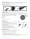
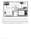
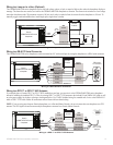
This cable is supplied with the GPSMAP 7015/7215 chartplotters, and it is not compatible with any other GPSMAP 6000/7000 series
chartplotter. This cable connects to the purple connector on the back of the GPSMAP 7015/7215 chartplotter, and it allows two additional
composite video sources, an S-Video source, and PC VGA input.
➌
➌
➍
➎
➌
Video 3 and Video 4 inputs (RCA connectors) allow two NTSC/PAL compatible composite video devices, such as a VCR, a DVD player,
a TV, or a video camera. The GPSMAP 7015/7215 chartplotter can display up to four video inputs at a time, or it can cycle through all
connected video inputs. See the GPSMAP 6000/7000 Series Owner’s Manual for details. Sound from a video source must be attached to a
separate stereo/audio system.
➍
Connect a computer to the PC monitor input (HD 15-pin) connector to use the GPSMAP 7015/7215 chartplotter as a computer monitor. See
the GPSMAP 6000/7000 Series Owner’s Manual for details.
➎
S-Video input (S-Video connector) allows input of NTSC/PAL compatible S-Video devices, such as a VCR, a DVD player, a TV, or a video
camera. An S-Video connection provides a higher-quality video signal than a composite video connection.