


GPSMAP 6000/7000 Series Installation Instructions 7
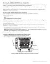
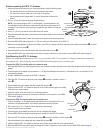
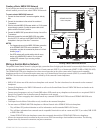
1. Routethecableawayfromsourcesofelectronicinterferencesothatthecableconnectorisatthemountinglocationofthechartplotter.
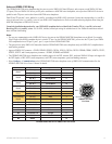
2. Usethetableabovetoidentifythecorrectlockingringforthecable,andlocatethelockingringbagbynumber.
3. Separatethetwohalvesofthelockingring.
4. Alignthetwohalvesofthelockingringoverthecableandsnapthemtogether.
5. InserttheO-ringintotheendoftheconnector.
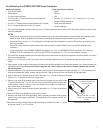
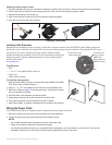
Depending on the installation, it may be necessary to drill holes to route the connector end of the GPSMAP cables. Rubber grommets are
provided to cover the cable holes for a nished look. You may not need the grommets in some installations. The grommets do NOT create a
waterproof seal. To create a waterproof seal, apply a marine sealant around the
grommet and cable after installation. Be sure to test the system before installing and
sealing the grommets. Purchase additional grommets from your Garmin dealer or
directly from Garmin at
www.garmin.com.
• Drill
• 1
1
/
4
in. (31.7 mm) paddle drill bit or hole saw
• Utility knife
• Marine sealant (optional)
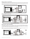
1. Markthelocationwhereyouwanttoroutethecable(power,NMEA0183,NMEA
2000,MarineVideo,orMarineNetwork.)
2. Usinga1
1
/
4
in.(31.7mm)paddledrillbitorholesaw,drilltheinstallationhole.
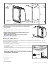
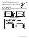
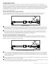
3. Refertothediagramonpage7fortrimminginstructions.Carefullytrimthecable
holeinthegrommet,asneeded.
4. Routethecabletothechartplotter,andtestthesystem.
5. Spreadthegrommetapartatthesplitandplaceitaroundthecable.
6. Firmlypushthegrommetintotheinstallationholeuntilitisseated.
7. Applymarinesealant,asneeded,toweatherprooftheinstallation-hole(optional).
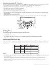
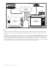
The GPSMAP 6000/7000 series chartplotter must be connected to the power supply for the boat.
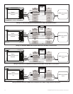
1. Routetheincluded2-pinpowercabletotheboatbatteryandtothechartplotter.
2. Connectthepower(red)andground(black)wirestothebatteryterminals.
• Use14AWGshieldedwiringforextendedrunsofwiretothepowercable.
• Solderallconnectionsandsealthemwithheat-shrinktubing.
• Ifyourboathasanelectricalsystem,youcanpossiblywirethechartplottertoanunusedholderonyourfuseblock.Ifyouwirethe
chartplottertothefuseblock,removethein-linefuseholdersuppliedwiththe2-pinpowercable.
Trim to this line for the
Marine Video cable.
Use this hole (no
trim) for a power,
NMEA 0183,
Marine Network, or
NMEA 2000 cable
Split