


GPSMAP 6000/7000 Series Installation Instructions 3
• Flush-mounttemplate
• Rubbergasket
• Fourush-mountnut-plates
• Four60mmM30.5screws(tosecurethenutplatetothe
mountingsurface)
• FourM40.7screws(tosecurethechartplottertothenutplate)
• Four7mmnylonwashers(fortheM40.7screws)
• Jigsaw
• Scissors
• Drill
• Drillbits—
3
/
8
in.(9.5mm),
9
/
32
in.(7.2mm),and
9
/
64
in.(3.5mm)
• Number2Phillipsscrewdriver
• Centerpunchandhammer
• Fileandsandpaper
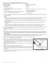
1. Theush-mounttemplateisincludedintheproductbox.Trimthetemplateandensurethatitwilltinthelocationatwhichyouwanttoush
mountthechartplotter.
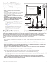
• Ensurethatthesurfaceonwhichyoumountthechartplotterhasenoughopenspacebehindittoaccommodatethechartplotterandthe
connectedwires.Refertothediagramontheush-mounttemplatefortheclearance-spaceneededbyyourchartplotter.
• Ensurethatthereisatleast
1
/
2
in.(13mm)ofspaceontherightsideofthechartplottertoaccesstheSDcarddoor,asindicatedonthe
ush-mounttemplate.
• Ensurethatenoughventilationispresentbehindthemountingsurfacetocreatesufcientairowtopreventthechartplotterfrom
overheating.
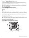
• Toavoidinterference,mountGPSMAP6008/6208chartplotters15in.(38.1cm),GPSMAP6012/6212chartplotters16in.(40.6cm),
GPSMAP7012/7212chartplotters25in.(63.5cm)and7015/7215chartplotters17in.(43.2cm)fromamagneticcompass.
2. Theush-mounttemplatehasadhesiveontheback.Removetheprotectivelinerandapplythetemplatetothelocationatwhichyouwantto
ushmountthechartplotter.
3. Usinga
3
/
8
in.(9.5mm)drillbit,drilloneormoreofthefourpilotholesinsidethecornerofthetemplatetobegincuttingthemounting
surface.
4. Usingajigsaw,cutthemountingsurfacealongtheinsideofthesolidlineindicatedontheush-mounttemplate.Usealeandsandpaperto
renethesizeofthehole.
.
5. Placethechartplotterintheholeandensurethatthemountingholesonthechartplotterlineupwiththelarger
9
/
32
in.(7.2mm)holesonthe
ush-mounttemplateaftercutting,sanding,andlingthehole.Iftheydonotlineup,marknewlocationsforthelargerholes.
6. Usingacenterpunch,indentthecenterofeachofthelarger
9
/
32
in.(7.2mm)mounting-holelocations.
7. Usinga
9
/
32
in.(7.2mm)drillbit,drillthefourlargerholes.
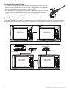
8. Startinginonecornerofthetemplate,placeanutplateoverthelargerholeyoudrilledinstep
7.Ensurethatthesmaller
9
/
64
in.(3.5mm)holeonthenutplatelinesupwiththesmallerhole
onthetemplate.Iftheydonotlineup,markanewlocationforthesmallerhole.Repeatthis
stepforeachcornerofthetemplate.
9. Usingacenterpunch,indentthecenterofeachofthesmaller
9
/
64
in.(3.5mm)mounting-hole
locations.
10.Removetheush-mounttemplatefromthemountingsurface.
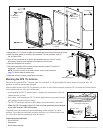
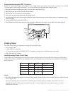
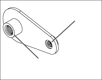
11.Startinginonecornerofthemountinglocation,placeanutplateonthebackofthemounting
surface,liningupthelargeandsmallholes.Theraisedportionofthenutplateshouldtinto
thelargerhole.
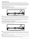
12.Securethenutplatetothemountingsurfacebyfasteninganincluded60mmM3×0.5screw
throughthesmaller
9
/
64
in.(3.5mm)hole.
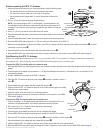
Use the 60 mm M3 × 0.5 screw
to fasten the nut plate to the
mounting surface
Use the 70 mm M4 × 0.7 screw
to fasten the chartplotter to the
nut plate