


307985 5
Installation
General Information
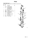
NOTE: Reference numbers and letters in parentheses
in the text refer to the callouts in the figures and the
parts drawing.
NOTE: Always use Genuine Graco Parts and Acces-
sories, available from your Graco distributor. If you
supply your own accessories, be sure they are ade-
quately sized and pressure rated for your system.
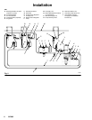
Fig. 2 is only a guide for selecting and installing sys-
tem components and accessories. Contact your Graco
distributor for assistance in designing a system to suit
your particular needs.
Prepare the Operator
All persons who operate the equipment must be
trained in the safe, efficient operation of all system
components as well as the proper handling of all fluids.
All operators must thoroughly read all instruction
manuals, tags, and labels before operating the equip-
ment.
Grounding
WARNING
FIRE AND EXPLOSION HAZARD
Before operating the pump, ground the
system as explained below. Also read
the section FIRE AND EXPLOSION
HAZARD on page 3.
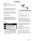
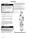
1. Pump: order Part No. 237569 Ground Wire and
Clamp. See Fig. 1. Loosen the grounding lug
locknut (W) and washer (X). Insert one end of the
ground wire (Y) into the slot in lug (Z) and tighten
the locknut securely. Connect the other end of the
wire to a true earth ground.
Fig. 1
W
X
Y
Z
0864
2. Air and fluid hoses: use only electrically conductive
hoses.
3. Air compressor: follow manufacturer’s recommen-
dations.
4. Spray gun: ground through connection to a proper-
ly grounded fluid hose and pump.
5. Fluid supply container: follow your local code.
6. Object being sprayed: follow your local code.
7. Solvent pails used when flushing: follow your local
code. Use only metal pails, which are conductive,
placed on a grounded surface. Do not place the
pail on a nonconductive surface, such as paper or
cardboard, which interrupts the grounding continu-
ity.
8. To maintain grounding continuity when flushing or
relieving pressure, hold a metal part of the spray
gun firmly to the side of a grounded metal pail,
then trigger the gun.
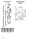
Mounting the Pump
Mount the pump to suit the type of installation planned.
The pump dimensions and mounting hole layout are
shown on page 16.
If the pump is immersed, be sure the pump intake is
1/2 in. (13 mm) off the bottom of the fluid container.
If the pump is mounted on the wall or on a stand,
connect a suction line to the pump’s 1–1/2 in. npt(f)
fluid inlet and place the other end of the line in the fluid
container.