


307985 7
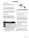
Installation
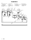
Available Accessories (must be
purchased separately)
Air Line Accessories
WARNING
A bleed-type master air valve (A) is required in your
system to help reduce the risk of serious injury,
including splashing of fluid in the eyes or on the
skin, and injury from moving parts if you are adjust-
ing or repairing the pump.
The bleed-type master air valve relieves air trapped
between this valve and the pump after the air is
shut off. Trapped air can cause the pump to cycle
unexpectedly. Locate the valve close to the pump.
D The bleed-type master air valve (A) is required in
your system to relieve air trapped between it and
the air motor when the valve is closed (see the
WARNING above). Be sure the bleed valve is
easily accessible from the pump, and is located
downstream from the air filter/regulator (B). Order
Part No. 113269 Bleed Valve.
D The air filter/regulator (B) controls pump speed
and outlet pressure by adjusting the air pressure to
the pump and the air spray gun. It also removes
harmful dirt and moisture from the compressed air
supply. Locate the pump air filter/regulator up-
stream from the pump’s bleed-type master air
valve (A). Also, supply an air filter/regulator at each
spray booth.
D A pump runaway valve (R) automatically shuts off
the pump if it starts running too fast. A pump which
runs too fast can be seriously damaged.
D An air line lubricator (C) provides automatic air
motor lubrication. Install downstream from the
pump air filter/regulator (B).
D Install additional air bleed valves (N) at each air
line drop, to isolate accessories for servicing.
Fluid Line Accessories
WARNING
A fluid drain valve (D) is required in your system to
help reduce the risk of serious injury, including
splashing of fluid in the eyes or on the skin.
The fluid drain valve assists in relieving fluid pres-
sure in the displacement pump, hose, and gun.
Triggering the gun to relieve pressure may not be
sufficient.
D The fluid drain valve (D) is required in your sys-
tem to relieve fluid pressure in the hose and gun
(see the WARNING above).
D Install a surge tank (E) to reduce fluid line pulsa-
tions.
D Install two fluid filters (G) to remove impurities
from the fluid before it reaches the spray gun (J).
Install fluid shutoff valves (F) upstream and down-
stream from each filter; this arrangement enables
you to continue spraying while cleaning a filter.
D Install a fluid pressure regulator (H) to provide
precise fluid pressure control at each spray booth.
D Install fluid shutoff valves (F) where shown.
Fluid Return Line
D Install a main fluid return line (S) to circulate fluid
back to the pump’s return port.
D Install a secondary fluid return line (T) to circu-
late fluid from the spray guns back to the fluid
supply container.
D Install a back pressure regulator (K) on each
fluid return line, after the last gun station, to provide
constant system back pressure for all spray guns
and proper pressure for fluid circulation.