


Reciprocator Repair
312350K 17
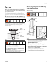
9. Use a spanner wrench to screw piston (22) onto
displacement rod (34). Torque to 40 to 48 ft-lb (54 to
65 N.m).
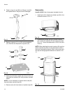
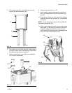
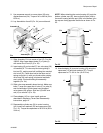
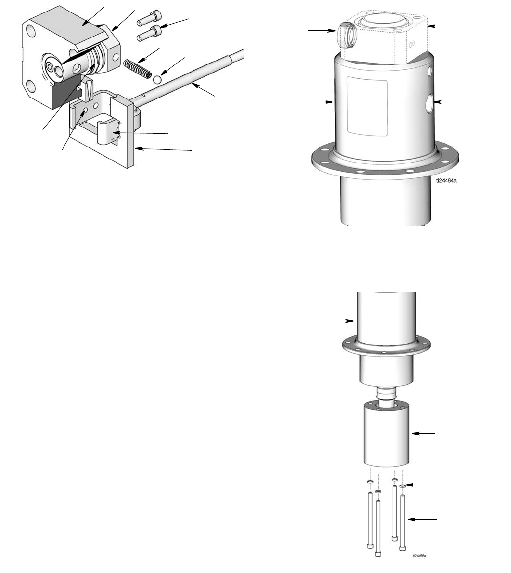
10. Lay Assemblies A and B (F
IG. 24) on work bench.
11. Slide Assembly B in into center of tool (D), Part No.
189305. Align upper detent holes (C) of yoke (9)
with center line of tool (D) (F
IG. 24).
12. Insert spring (6) and one ball (7) into valve stop (26)
of Assembly A. Tilt valve stop and start guiding it
into tool (D), making sure ball is sliding into rounded
slot in tool (D). Place other ball at the other end of
spring and push it in with your thumb while rotating
valve stop (26) until spring is horizontal and balls
are in place. Continue holding this assembly
together (F
IG. 24).
13. Slide valve stop assembly down into tool. Make sure
balls (7) snap into upper set of holes (C) in yoke (9)
and curved ends of guide clamp have engaged
valve sleeve (29) groove. Slide tool (D) back over
rod (12) to remove it (F
IG. 24).
14. Place adapter (43) in a vise. Install seals as
described in Replacing Throat Seal Reassembly
instructions, page 12.
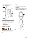
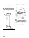
15. Reassemble cylinder cap (32) to motor housing
(43). Install lock washers (52) and cap screws (46)
(F
IG. 13). Torque the capscrews to 28-32 ft-lb (38 to
43 N.m).
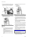
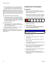
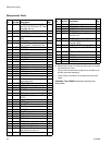
NOTE: When attaching the motor housing (43) onto the
bottom cylinder cap (32), be sure that the port (43b) in
the motor housing and the port (32b) in the bottom cylin-
der cap are facing opposite directions as shown in F
IG.
25.
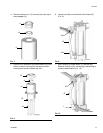
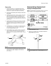
16. Attach adapter (8) to motor housing (43) using four
capscrews (15) and lock washers (27). Torque
capscrews to 170-180 in.-lbs (19-20 N.m).
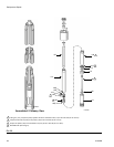
FIG. 24
9
ti10606a
12
D
C
7
6
Assembly A
Assembly B
31
26
51
29
FIG. 25
FIG. 26
32b
32
43b
43
8
43
27
15