


Operation
312350K 7
Operation
Before Starting Pump
• Check hydraulic fluid level in hydraulic power supply
before each use. Add fluid as necessary to fill the
lines.
• Flush pump before using it for the first time to
remove the light oil that was left in after factory test-
ing to protect pump from corrosion. Be sure solvent
used is compatible with the fluid to be pumped and
the pump’s wetted parts. See Technical Data, page
26. Flush until clean solvent comes out of hose.
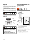
Starting Pump
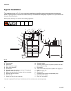
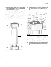
For the following instructions, see FIG. 2.
1. Turn on hydraulic power supply.
2. Open return line shut-off valve (H) first, then slowly
open the hydraulic supply shut-off valve (L).
3. Adjust flow control valve (Q) to limit the hydraulic
flow to no more than 3 gpm (11 lpm), which is
approximately 60 cycles per minute.
4. Adjust pressure reducing valve (N) to increase
hydraulic inlet pressure from 50 to 600 psi (0.34 to
4.1 MPa, 3.4 to 41 bar).
• Increasing inlet pressure, increases outlet pres-
sure.
• Decreasing inlet pressure, decreases outlet
pressure.
5. Open drain valve while priming pump.
6. When pump is primed, close drain valve.
Shutdown
Relieve pressure, page 5, whenever you shutdown.
NOTICE
To prevent damage to pump, do not operate pump
without it being securely mounted to a drum cover or
support.
COMPONENT RUPTURE HAZARD
Overpressurizing any component can result in serious
injury or property damage as a result of rupture, fire, and/or
explosion.The maximum working pressure of each
component in the system may not be the same. To reduce
the risk of overpressurizing any component in the system:
• Be sure you know the maximum working pressure of
each component.
• Never exceed the maximum working pressure of the
lowest rated component in the system.
• Do not exceed the maximum pump cycle rate.
• The pump has a rated ratio of 10:1. However, it is
capable of reaching stall pressures equal to 12.5 times
the hydraulic input pressure. To calculate the fluid
output pressure, multiply the hydraulic pressure shown
on the hydraulic control module gauge by 12.5.
For example:
600 psi hydraulic x 12.5 = 7500 psi fluid output
4.14 MPa hydraulic x 12.5 = 51.8 MPa fluid
output
41.4 bar hydraulic x 12.5 = 5.18 bar fluid output
• Regulate hydraulic pressure to the pump so that no
fluid line component or accessory is overpressurized.
NOTICE
Always use lowest pressure possible to obtain desired
results. This reduces pump wear.
Maximum Working Pressures
To reduce the risk of serious injury, including fluid injection
and splashing in the eyes or on the skin, which may be
caused if a component ruptures:
• Never exceed 600 psi (4.1 MPa, 41 bar) Maximum
Hydraulic Pressure to the reciprocator.
• Never exceed 7500 psi (51 MPa, 517 bar) Maximum
Outlet Pressure from the displacement pump.
• Accessories added to the pump fluid outlet side should
have at least a 7500 psi (51 MPa, 517 bar) Maximum
Working Pressure.
• Read and understand COMPONENT RUPTURE
HAZARD instructions, page 7.