


Installation
6 312350K
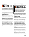
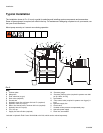
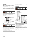
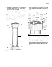
Typical Installation
The installation shown in FIG. 2 is only a guide for selecting and installing system components and accessories.
Some of the equipment is required, as noted in the key. For assistance in designing a system to suit your needs, con-
tact your Graco distributor.
Mount pump securely so it cannot move during operation.
Key:
A Follower plate
B Weep tube
C Fluid outlet line (to gun)
D Drain valve (required)
E Ground wire
F Hydraulic return line, minimum 3/4 inch I.D. (required)
G Hydraulic outlet, 3/4” npt (f)
H Return line shut-off valve, minimum 3/4 inch (required)
J Hydraulic inlet, 3/4” npt (m)
K Tee, 3/4” npt
L Supply line shut-off valve (required)
M *Pressure gauge
N *Pressure reducing valve (required in systems over 600
psi [4.1 MPa, 41 bar])
P Accumulator
Q *Flow control valve (required in systems over 3 gpm [11
lpm])
R Hydraulic supply line
S Check valve
T Variable volume pressure compensated pump
U Hydraulic power supply
V Drain line, accumulator
*Included in Hydraulic Fluid Control Kit 247538 or 247705, which can be ordered separately.
FIG. 2
ti0477a
U
T
S
R
Q
P
N
M
L
K
J
H
G
F
D
C
B
A
E