


22
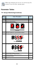
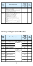
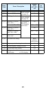
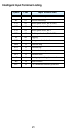
Intelligent Output Terminal Listing
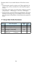
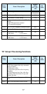
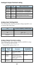
Analog Input Configuration
The following tables show the parameter settings required for vari-
ous analog input signal types.
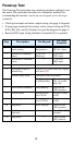
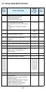
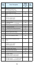
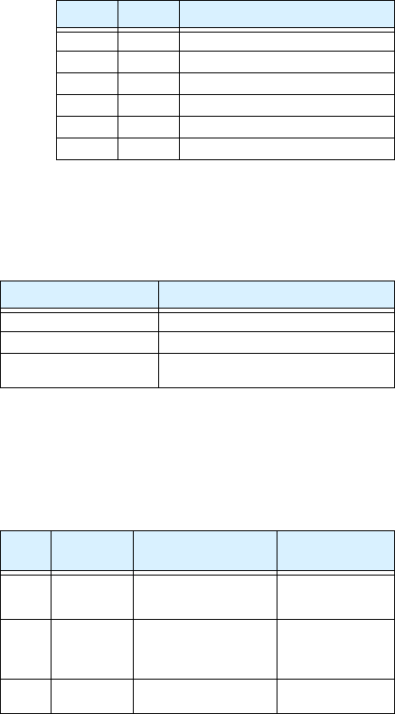
Analog Output Function Listing
The following table shows all three functions available for assign-
ment to the analog output terminal:
• Terminal [FM], option set by C_23
Symbol Code Input Terminal Name
RUN 00 Run signal
FA1 01 Freq. arrival type 1 – constant speed
FA2 02 Freq. arrival type 2 – over-frequency
OL 03 Overload advance notice signal
OD 04 Output deviation for PID control
AL 05 Alarm signal
[AT] External Frequency Command Input
OFF [O] — [L]
ON [OI] — [L]
(not assigned to any input
terminal)
Summation of [O] — [L] and [OI] — [L]
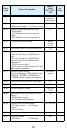
Option
Code
Function
Name
Description
Corresponding
Signal Range
00 Output
frequency
Actual motor speed,
represented by PWM
signal
0 to max. freq. in Hz
01 Output
current
Motor current (% of
maximum rated output
current), represented by
PWM signal
0 to 200%
02 Digital output
frequency
Output frequency 0 to max. freq. in Hz