


2
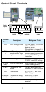
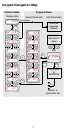
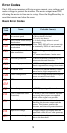
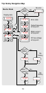
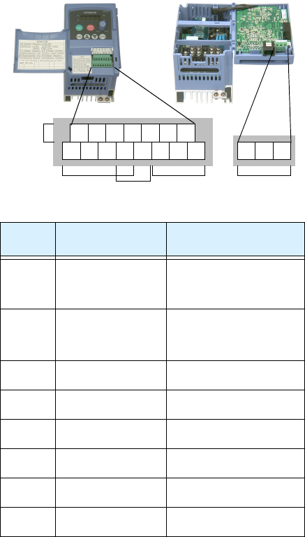
Control Circuit Terminals
Terminal
Name
Description Ratings and Notes
P24 +24V for logic inputs 24VDC supply, 30 mA max.
(Notes: Do not use for
network power
Do not short to terminal L)
1, 2, 3, 4,
5
Intelligent (program-
mable) discrete logic
inputs
27VDC max. (use P24 or an
external supply referenced to
terminal L), 4.7kΩ input
impedance
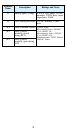
11, 12 Discrete logic outputs 50 mA max. ON current,
27 VDC max. OFF voltage
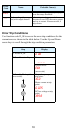
L (top
row)
GND for logic inputs Sum of input 1 to 5 currents
(Note: Do not ground)
CM2 Common for logic
outputs
100 mA max for sum of
terminals 11 and 12 currents
FM PWM output 0 to 10VDC, 1 mA max.,
50% duty cycle
L (bottom
row)
Common for analog
inputs
Sum of OI, O, and H
currents (return)
OI Analog input, current 4 to 19.6 mA range, 20 mA
nominal
H O OI
FM
P24
L
Analog
inputs
Analog
outputs
Alarm
relay
Logic
outputs
Logic
inputs
L
5 4 3 2 1
CM2
12 11
AL0 AL1 AL2