


FUNC
RUN
FUNC
FUNC
STR
STOP
RE
S
ET
58.1
58.0
57.9
F02
F02
d01
d02
d03
d04
d05
d06
d07
d08
d09
F01
F02
F03
F04
A
--
b
--
C
--
H
--
F202
F203
or
After the data is
changed, press the
STR ke
y
to save data
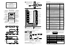
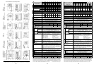
[FUNC key] ... This key switches
between the parameter area, data
area, and extended function area.
Each time the key is pressed, the
display changes as follows:
Pressing the FUNC key
leaves data unchanged
[UP key, DOWN key] ... These keys change the
values of data area, and parameters:
Output frequency
monitor
Output current
monitor
Running direction
monitor
PID feedback
monitor
Input terminal
status
Output terminal
status
Scaled output
frequency
Trip monitor
Trip history
monitor
Set the output
frequency
Set acceleration
time 1
Set deceleration
time 1
Set motor
direction
Group A exten-
ded functions
Group B exten-
ded functions
Group C exten-
ded functions
[START key] ... This key starts
the SJ100 inverter.
The set value of
F004
deter-
mines forward or reverse run.
[STOP key] ... This key
stops the SJ100 inverter.
When a trip occurs, this key
becomes the RESET ke
y
Group H exten-
ded functions
Set acceleration
time 1
(
2. settin
g)
Set deceleration
time 1 (2. settin
g
)
When an extended function is to be used, select the
extended function group from , ,
, or by using the two keys
and so as to enter the extended function mode.
FUNC
FUNC
FUNC
STR
FUNC
Extended function
parameter number
Extended function data
Return to extended
function parameter
and memorize
Return to extended
function parameter and
do NOT memorize
Explanation of display at power on
When the inverter is turned on, the display returns to what was displayed when the power
was last turned off (exce
p
t in the extended function mode).
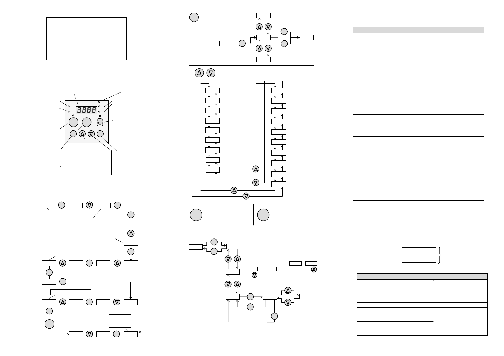
Settin
g
extended functions
(
exam
p
le for
g
rou
p
A extended functions
)
A
--
A01
A02
A24
0
40
A -- b --
C --
Extended functions are
entered from
A -
-
using
the FUNC key. Follow-
ing this, the function
parameter number is
displayed for which
data had been entered
last.
After changes to data
have been made, the
FUNC key or STR key
must be pressed. When
the FUNC key is being
pressed once more,
control is returned back
to
A -
-
.
H --
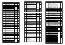
Trip Contents Display
Overcurrent
protection
When the output of the inverter is short circuited,
the motor is locked, or a heavy load is suddenly
applied, and the inverter output current exceeds a
predetermined level, the inverter is shut off.
C
onst
.
s
p
eed
:
E001
At decelerat
.:
E002
At accelerat
.:
E003
At the others:
E004
Overload
protection
When a motor overload is detected by the electronic
thermal function, the inverter is shut off.
E005
Braking resis-
tor overload
When the operation of the braking resistor exceeds a
certain time duration, the inverter is shut off.
E006
Overvoltage
protection
When the inverter DC bus voltage exceeds a pre-
determined level due to regenerative energy from the
motor, this trip occures and the inverter is shut off.
E007
EEPROM error
(NOTE 1)
When the inverter memory has a problem due to
noise or excessive temperature rise, this trip occurs
and the inverter is shut off.
E008
Undervoltage
protection
A decrease of DC bus voltage may result in improper
function of the control unit. It may also cause motor
heating and low torque. The inverter is shut off when
the DC bus voltage goes below a certain level.
E009
CT error When a large noise source is near the inverter or an
abnormality occurs on built-in CT, inverter output is
cut off.
E010
CPU error Malfunction or abnormality of the CPU. The inverter
is shut off.
E011
E022
External trip A trip signal from external equipment shuts off the
inverter. It is necessary to assign the external trip to
an intelligent terminal.
E012
USP error Indicates an error when power is turned on while the
inverter run is enabled
(
with USP function selected
)
.
E013
Ground fault
protection
The inverter is protected by detection of ground
faults between the drive output and the motor at
power on. Protection is for the inverter only and not
for humans.
E014
Input
overvoltage
When the input voltage is higher than a specified
value, it is detected and 100 seconds after power is
turned on, the inverter is shut off.
E015
Thermal
protection
When the temperature of the inverter module is bey-
ond specification, the built-in thermal sensor detects
the temperature and the inverter is shut off.
E021
PTC error When the resistance value of the external thermistor
is too large, the equipment detects the abnormal
condition of the thermistor and then shuts off the
inverter (when PTC function is selected).
E035
Waiting
(
undervolta
g
e
)
Waiting with the output turned off, because the
inverter receiving voltage has dropped.
_
_
U
SJ100
This information is written on
the nameplate located on the
right side of the SJ100 inverter.
Display Function
Standard Setting
Set Value
d
0
1
..
.. d 09
Display functions Refer to page 4
F 01
Set output frequency (Hz) 0.0
F 02
Set acceleration 1 (s) 10.0
F202
Set acceleration 1 (s), 2. setting 10.0
F 03
Set deceleration 1 (s) 10.0
F203
Set deceleration 1 (s), 2. setting 10.0
F 04
Set motor direction 00 (rechts)
A --
Set extended function group A
b --
Set extended function group B
C --
Set extended function group C
H --
Set extended function group H
Refer to pages 6 through 8
Mf
g
.No.
Protective Functions
The SJ100 series inverter will trip on overcurrent, overvoltage and undervoltage to protect the
inverter.The output is shut down and the motor runs free. This condition is held until it is reset.
SJ100 data setting values
SJ100 inverters provide many functions whose parameters can be
set by the user. It is recommended that the parameters that have been set by the user be recorded
Drive keypad display sequence
N
OTE
1: If an EEPROM error occurs, be sure to observe ist value. If power is turned off while the
[RS] input terminal is held ON, the EEPROM error occurs when power is turned back on.
in order to speed the
investigation and re-
pair in the event of
a failure.
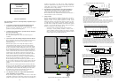
Power Lamp
Power Lamp of
Control Circuit.
Hz or A Lamp
Hz or A lamp is on
during display of
fre
q
uenc
y
or current.
Potentiometer
This potentiometer
sets the frequency (the
lamp is on when the
potentiometer is
available for speed
settin
g)
.
STR Key
Press this key after
setting data and
parameters to store
them in memory.
UP/+ Key, DOWN/- Key
These keys are used to change data and parameters
FUNC Key
This key is used
for setting up data
and parameters.
RUN Key
This key is used for
starting. (When
terminal run is
selected this key does
not function and the
lamp is off. The lamp
is on when this key is
available)
PRG Lamp
This lamp is on
while a parameter is
bein
g
set.
RUN Lamp
This lamp is on when
the inverter is
running or the run
command is active.
Monitor (LED Display)
This display shows frequency,
motor current, DC voltage,
motor direction, and parameters.
STOP Key
This key is used for stopping
the motor or resetting errors or
trips. (When the keypad is
selected, this key is functional;
non-functional using remote).
MIN MAX
FUNC
RUN
STOP
RESET
A
HzRUN
PRG
POWER
HITACHI
STR
HITACHI INVERTER
SJ100 SERIES
QUICK REFERENCE GUIDE (Part 1/2)
Single phase input 200V class
Three phase input 200V class
Three phase input 400V class
FUNC
RUN
FUNC
FUNC
STR
FUNC
STR
FUNC
FUNC
FUNC
Hz
Turn
p
ower on.
(4
x)
Data is
stored
(6
x)
Press
continuousl
y
Data is
stored
STR
Start
run
(Motor operates)
(9
x)
Monitoring
actual output
fre
q
uenc
y
Extended
function of
A Grou
p
Operation procedure (example for the digital operator)
0.0
d01
A
--
A01
01
02
A01
A02
01
02
A02
060.0
0.0
F01
A
--
60.0
d01
F01
Data is stored
Frequency set value set by
function
F 01
(instead of
analo
g
in
p
ut
)
Settin
g
fre
q
uenc
y
to 60Hz
Starting command via RUN key
(instead of terminal FW/RV)
3 4 5