


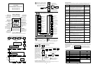
5 4321P24
H
OOILFMCM
2
12 11
AT
24VDC
6
H
L
Reverse
Forward
Common for
in
p
ut si
g
nals
Frequency mete
r
(0..10V, 1mA)
Motor thermisto
r
(PTC)
Set valu
e
(4...20mA)
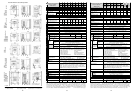
A 01
= 01 (Frequency set value on input O or OI)
A 02
= 01 (Start signal on FW/RV)
F 02
= 10 (acceleration time 10 sec.)
F 03
= 10 (deceleration time 10 sec.)
C 01
= 00 (FW: Start forward run via input 1)
C 02
= 01 (RV: Start reverse run via input 2)
C 03
= 16 (AT: Use current input 4-20mA for set value)
C 05
= 19 (PTC on input 5)
The inverter can now be started via input 1 (forward run) or input 2 (reverse run). If the
inputs RV and FW are both closed, the inverter is stopped. If input AT is configured as
normall
y
o
p
en contact and is closed
,
current in
p
ut on
O
I is used for set
v
alue
.
Wirin
g
exam
p
le: Set value 4..20mA and thermistor
65
4321P24
HOOILFMCM21211
AT
24VDC
CF1
CF2
+24V
RUN
FA1
L
Reverse
Forward
Common for
in
p
ut si
g
nals
Frequency meter
(
0..10V
,
1mA
)
Wiring example: Fixed set values; FA1 output and RUN output
Parameters for functions
A 01
,
A 02
,
F 02
,
F 03
,
C 01
,
C 02
, and
C 03
are set exactly the
same as in the example above. Additionally,
C 04
is set to 02 (CF1) and
C 05
is set to 03
(CF2). Fixed frequency set values are set via functions
A 21
,
A 22
, and
A 23
using parame-
ters 0 to 360 (= frequency 0 to 360Hz). The inverter can now be started via input 1 (FW) or
input 2 (RV). If the inputs RV and FW are both closed, the inverter is stopped. If none of the
di
g
ital in
p
uts CF1 or CF2 is closed, fre
q
uenc
y
set value can be set usin
g
analo
g
in
p
uts O/OI.
P
A 72
0-300 l/h
= 0-100%)
I
A 73
D
A 74
+
+
+
F 01
+
Display
d 04
A 76 =
01
[PID current value at
terminals (O-L)]
0 – 10V = 0 – 500 l/h
A 01
= 01 (fixed set values)
A 21
= 100 l/h (=33%)
A 22
= 200 l/h (=66%)
A 23
= 300 l/h (=100%)
A 75
= 3.00
A 75
= 3.00
Frequency set value
0-100% =50Hz; limited to 10Hz min.
0-6V-10V
Set value is given in fixed intervals: 100, 200, 300l/h. The current value is input by a sensor (0-
500l/h = 0-10V). When the difference is greater than 20% a warning is output. The frequency
must not fall below 10 Hz. The set value and current value are displayed as flow rate in l/h
(300l/h = 100% = 50Hz maximum frequency).
In order to display the correct value,
A 75
is set to 3.00 so that a set value of 100% corres-
ponds to a flow rate of 300l/h. In order to match the current value input (0-500l/h) to the set
value input (0-300l/h) the current value must be adjusted with parameters
A 11
to
A 14
, i.e.
A 14
must be set to 60% so that 300l/h process value corresponds to 100% current value.
Application example: Flow control
A flow control circuit is to be realized using the SJ100 inverter built in PID control.
0-300 l/h
= 0-6V
= 0-100%)
+
Flow rate
set value
Q
set
-
M
Flow rate current value Q
cur
f
cur
A 14 = 60%
set value adjustment
-
HITACHI INVERTER
SJ100 SERIES
QUICK REFERENCE GUIDE (Part 2/2)
Single phase input 200V class
Three phase input 200V class
Three phase input 400V class
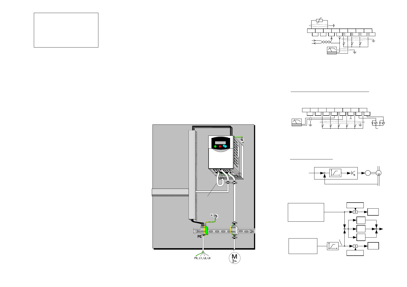
CE-EMC Installation
This instruction describes the electromagnetically compatible setup o
f
your drive system.
1. As an enduser you must ensure that the HF impedance between
frequency inverter, filter and ground is as small as possible.
•
See to it that the connections are metallic and have the largest
possible areas (zink-plated mounting plates)
2. Conductor loops act like antennas, especially when they encompass
large areas. Consequently:
•
Avoid unnecessary conductor loops
•
Avoid parallel arrangement of „clean“ and interference-prone
conductors
3. Lay the motor cable and all analog and digital contol lines shielded.
•
You should allow the effective shield area of these lines to remain as
large as possible; i.e., do not move the shield further away than
absolutely necessary.
•
With compact systems, if for example the frequency inverter is
communicating with the steering unit, in the same control cabinet
connected at the same PE-potential, the screen of control lines should
be put on, on both sides with PE. With branch systems, if for example
the communicating steering unit is not in the same control cabinet and
there is a distance between the systems, we recommend to put on the
screen of control lines only on the side of the frequency inverter. If it is
possible, direct in the cable entry section of the steering unit. The
screen of Motor cabels always must be put on, on both sides with PE.
•
The large area contact between shield and PE-potential you can
realise with a metal PG screw connection or a metallic mounting clip.
•
Use only copper mesh cable (CY) with 85% coverage
•
The shielding should not be interrupted at any point in the cable. If
the use of reactors, contactors, terminals or safety switches in the motor
output is necessary, the unshielded section should be kept as small as
possible.
•
Some motors have a rubber gasket between terminal box and motor
housing. Very often, the terminal boxes, and particularly the threads for
the metal PG screw connections, are painted. Make sure there is always
a good metallic connection between the shielding of the motor cable,
the metal PG screw connection, the terminal box and the motor
housing, and carefully remove this paint if necessary.
4. Very frequently, interference is coupled in through installation
cables. This influence you can minimize:
•
Lay interfering cables separately, a minimum of 0.25 m from cables
susceptible to interference.A particularly critical point is laying cables
parallel over larger distances. If two cables intersect, the interference is
smallest if they intersect at an angle of 90°. Cables susceptible to
interference should therefore only intersect motor cables, intermediate
circuit cables, or the wiring of a rheostat at right angles and never be
laid parallel to them over larger distances.
5. The distance between an interference source and an interference
sink (interference-threatened device) essentially determines the
effects of the emitted interference on the interference sink.
•
You should use only interference-free devices and maintain a
minimum distance of 0.25 m from the drive.
6. Safety measures
•
Ensure that the protective conductor terminal (PE) of the filter is
properly connected with the protective conductor terminal of the
frequency inverter. An HF ground connection via metal contact
between the housings of the filter and the frequency inverter, or solely
via cable shield, is not permitted as protective conductor connection.
The filter must be solidly and permanently connected with the ground
potential so as to preclude the danger of electric shock upon touching
the filter if a fault occurs. You can achieve this by:
- connecting it with a grounding conductor of at least 10 mm
2
;
- connecting a second grounding conductor, connected with a
separate grounding terminal, parallel to the protective conductor
(The cross section of each single protective conductor terminal
must be designed for the required nominal load)
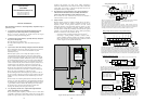
HITACHI
55.0
RUN
STOP
RESET
MI MAX
RUN
PRG
Hz
A
POWER
2
STR
FUNC.
1
SJ1 00
WARNING
HAZARD OF PERSONAL INJURY OR
ELECTRIC SHOCK
Disconnect incoming power and wait
5 minutes before opening front case.
PE connection
Figure: Hitachi frequency inverter with footprint filter
9 10 11