


002
N
FE
004
N
FE
005
N
FE
007
N
FE
011
N
FE
015
N
FE
022
N
FE
055
LFR
075
LFR
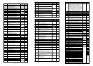
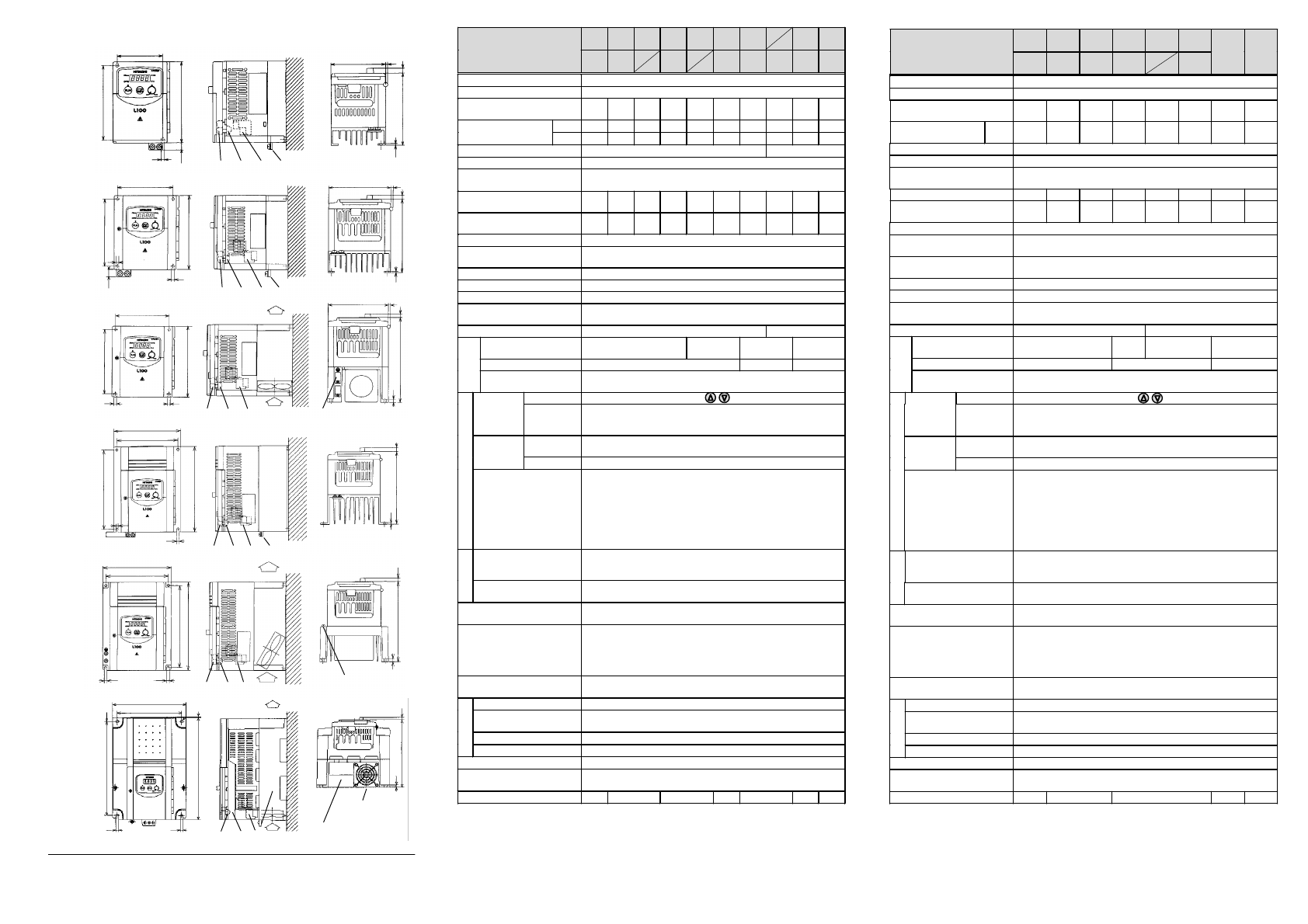
Technical S
p
ecifications
Inverter SJ100
-
(200V Series)
002
NFU
004
NFU
007
NFU
015
NFU
022
NFU
037
LFU
055
LFU
075
LFU
Protective structure (Note 1)IP20
Overvoltage category III
Maximum motor size (4P)
in kW (Note 2)
0.2 0.4
0.55
0.75 1.1 1.5 2.2
3.7 5.5 7.5
230V
0.6 1.0 1.1 1.5 1.9 3.1 4.3 6.9 9.1 12.2Maximum capacity
in kVA
240V
0.6 1.0 1.2 1.6 2.0 3.3 4.5 7.2 9.1 12.2
Input supply phase Single / Three phase Three phase
Rated input voltage 200VAC -10% ~ 240VAC +5% 50/60Hz +/-5%
Rated output voltage
(Note 3)
Three phase 200 ~ 240VAC
(Corresponds to input voltage)
Rated input current in A
Single phase (Three phase)
3.5
(2.0)
5.8
(3.4)
6.7
(3.9)
9.0
(5.2)
11.2
(6.5)
17.5
(10.0)
24.0
(14.0)
-
(22.0)
--
Rated output current in A
(Note 4a)
1.4 2.6 3.0 4.0 5.0 8.0 11.0 17.5
24.0
32.0
Output frequency range 0.5 ~ 360 Hz (Note 5)
Frequency accuracy
(at 25°C +/-10°C)
Digital command: +/-0.01% of maximum frequency
Analog command: +/-0.1% of maximum frequency
Frequency setting resolution Digital setting: 0.1 Hz Analog setting: max. frequency / 1000
Voltage/frequency characterist. Constant, reduced or high starting (SLV) torque (Note 8)
Overload current capacity 150% during 60 seconds (once per 10 minutes)
Acceleration/deceleration time 0.1 ~ 3000 s in selectable linear and non-linear mode
(second acceleration/deceleration usable)
Starting torque (using SLV) >
200% >
180%
Dynam. braking, feedback
to capacitor (Note 6)2
approx. 100%
approx. 70%
approx. 20%
approx. 30%
External braking resistor approx. 150%
approx.
100%
approx.
80%
DC injection braking
Braking is on at the minimum frequency or less (minimum frequency,
braking time and braking force can be set)
Dig. operator
Settings using keys or potentiometer
Frequency
setting
External
signals
0-10VDC (input impedance 10k Ohm)
4-20mA (input impedance 250 Ohm)
Potentiometer 1k-2k Ohm, 1W (055 ~ 075LFU/LFR: 2W)
Dig. operator
Via keys RUN (for start) and STOP/RESET (for stop)
(Default setting: forward run)
Forward /
Reverse run
(Start/Stop)
Ext. signals Intelligent input terminals configurable as FW and RV
Intelligent input terminals
programmable as
FW: Forward run start/stop RV: Reverse run start/stop
CF1–CF4: Multistage speed JG: Jogging command
AT: Analog current input selection 2CH: 2.Accel./decel. time
FRS: Free run stop EXT: External trip
USP: USP function RS: Reset
SFT: Software lock PTC: Thermal protection
DB: Ext. DB input SET: 2. setting active
UP: Acceleration (Remote) DWN: Decelerat. (Remote)
Intelligent output terminals
programmable as
FA1/FA2: Frequency arrival signal
RUN: Motor running signal OL: Overload signal
OD: Deviation signal at PID control AL: Alarm signal
Frequency and current
monitoring
Connection of external analog meter (0-10VDC, max. 1mA) for
fre
q
uenc
y
or current
;
connection of external di
g
ital fre
q
uenc
y
meter
Fault alarm contact On when the inverter trips (1c contact).
Alternatively usable as intelligent output terminal
Other functions Autotuning, Automatic voltage regulation, retry; analog gain/vias
adjustment, frequency jump, upper/lower limiter, output frequency
display, trip history monitoring, carrier frequency setting, PID
control, automatic torque boost, USP function, 2. Setting function,
ON/OFF control of cooling fan, and many more
Protection functions Overcurrent, overvoltage, undervoltage, electronic thermal, temp-
erature abnormality, ground fault, overload, CT error, BRD error
Ambient temperature -10 ~ 50°C (Note 7)
Storage temperature and
humidity
-25 ~ 70°C (during short term transportation period only)
20 ~ 90% RH (no dew condensation)
Vibration Max. 5.9m/s
2
(=0.6g) at 10-55Hz
Installation location 1000m or less altitude indoors (IP54 or equivalent)
External color Grey
Options Remote operator, copy unit, cable for digital operator,
reactor for improving power factor, noise filter, OPE-J
Overall weight (approx.) 0.7 0.8 1.3 2.3 2.8 5.5 5.7
Braking
torque
Inputs
OutputsEnvironmental
004
HFE
007
HFE
015
HFE
022
HFE
030
HFE
040
HFE
Technical S
p
ecifications
Inverter SJ100
-
(400V Series)
004
HFU
007
HFU
015
HFU
022
HFU
040
HFU
055
HFE
HFR
HFU
075
HFE
HFR
HFU
Protective structure (Note 1)IP20
Overvoltage category III
Maximum motor size (4P)
in kW (Note 2)
0.4 0.75 1.5 2.2 3.0 4.0 5.5 7.5
Maximum capacity
in kVA
460V
1.1 1.9 2.9 4.2 6.2 6.6 9.9 12.2
Input supply phase Three Phase
Rated input voltage 380VAC -10% ~ 460VAC +10% 50/60Hz +/-5%
Rated output voltage
(Note 3)
Three Phase 360 ~ 460VAC
(Corresponds to input voltage)
Rated input current in A 2.0 3.3 5.0 7.0 10.0 11.0 16.5 20.0
Rated output current in A
(Note 4b)
1.5 2.5 3.8 5.5 7.8 8.6 13.0 16.0
Output frequency range 0.5 ~ 360 Hz (Note 5)
Frequency accuracy
(at 25°C +/-10°C)
Digital command: +/-0.01% of maximum frequency
Analog command: +/-0.1% of maximum frequency
Frequency setting resolution Digital setting: 0.1 Hz
Analog setting: max. frequency / 1000
Voltage/frequency characterist. Constant, reduced or high starting (SLV) torque (Note 8)
Overload current capacity 150% during 60 seconds (once per 10 minutes)
Acceleration/deceleration time 0.1 ~ 3000 s in selectable linear and non-linear mode
(second acceleration/deceleration usable)
Starting torque (using SLV) > 200% > 180%
Dynam. braking, feedback
to capacitor (Note 6)
approx. 100% approx.
70%
approx. 20% approx. 30%
External braking resistor approx. 150% approx. 100% approx. 80%
DC injection braking
Braking is on at the minimum frequency or less (minimum frequency,
braking time and braking force can be set)
Dig. operator
Settings using keys or potentiometer
Frequency
setting
External
signals
0-10VDC (input impedance 10k Ohm)
4-20mA (input impedance 250 Ohm)
Potentiometer 1k-2k Ohm, 1W (055 ~ 075LFU/LFR: 2W)
Dig. operator
Via keys RUN (for start) and STOP/RESET (for stop)
(Default setting: forward run)
Forward /
Reverse run
(S
tart
/S
to
p)
Ext. signals Intelligent input terminals configurable as FW and RV
Intelligent input terminals
programmable as
FW: Forward run start/stop RV: Reverse run start/stop
CF1–CF4: Multistage speed JG: Jogging command
AT: Analog current input selection 2CH: 2.Accel./decel. time
FRS: Free run stop EXT: External trip
USP: USP function RS: Reset
SFT: Software lock PTC: Thermal protection
DB: Ext. DB input SET: 2. setting active
UP: Acceleration (Remote) DWN: Decelerat. (Remote)
Intelligent output terminals
programmable as
FA1/FA2: Frequency arrival signal
RUN: Motor running signal OL: Overload signal
OD: Deviation signal at PID control AL: Alarm signal
Frequency and current
monitoring
Connection of external analog meter (0-10VDC, max. 1mA) for
frequency or current; connection of external digital frequency meter
Fault alarm contact On when the inverter trips (1c contact).
Alternatively usable as intelligent output terminal
Other functions Autotuning, Automatic voltage regulation, retry; analog gain/vias
adjustment, frequency jump, upper/lower limiter, output frequency
display, trip history monitoring, carrier frequency setting, PID
control, automatic torque boost, USP function, 2. Setting function,
ON/OFF control of cooling fan, and many more
Protection functions Overcurrent, overvoltage, undervoltage, electronic thermal, temp-
erature abnormality, ground fault, overload, CT error, BRD error
Ambient temperature -10 ~ 50°C (Note 7)
Storage temperature and
humidity
-25 ~ 70°C (during short term transportation period only)
20 ~ 90% RH (no dew condensation)
Vibration Max. 5.9m/s
2
(=0.6g) at 10-55Hz
Installation location 1000m or less altitude indoors (IP54 or equivalent)
External color Grey
Options Remote operator, copy unit, cable for digital operator,
reactor for improving power factor, noise filter, OPE-J
Overall weight (approx.) 1.3 1.7 2.8 5.5 5.7
Braking
torque
Inputs
OutputsEnvironmental
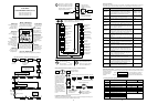
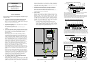
Legend:
A Control terminals B Alarm terminals
C Main terminals D Grounding terminal (All dimensions are in millimeters)
External dimensions and terminal positions
67
80
4
110
120
10
5
L
7
2,5
DCBA
L
= 93 (002NF)
107 (004/005NF)
98 110 4
118
130
10
5
129
7
2,5
DCBA
98
110
4
118
130
5
156
7
6
DCBA
5
Air
Air
Fan
140
180
153
7
3,5
DCBA
128
168
10
5
SJ100-
002 NFE/NFU
004 NFE/NFU 005 NFE
SJ100-
004 HFE/HFU
007 NFE/NFU 011 NFE
SJ100-
007 HFE/HFU (without fan)
015 HFE/HFU
022 HFE/HFU
SJ100-
015 NFE/NFU
140
CBA
5
Air
Air
128
5
168
180
164 7
D
6
Fan
SJ100-
022 NFE/NFU 030 HFE
037 LFU 040 HFE/HFU
182
CBA
7
Air
Air
160
7
257
7
D
236
170
6
Second fan built in with
inverters 075LFU/LFR.
Fan
SJ100- 055 LFU/LFR
055 HFE/HFU/HFR
075 HFE/HFU/HFR
075 LFU/LFR
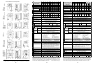
12 13 14
N
ote 1:
Protective structure is based upon EN60529. Note 2:
The applicable motor is a Hitachi
standard four-pole motor. When using another motor, make sure that the rated motor current does
not exceed the rated inverter current. Note 3:
The output voltage will decrease if input voltage
decreases. Note 4a:
The initial data setting values of 005N/011N are same as 004N/007N. So be sure
to set the values
b 12
and
b 22
of 004N/007N for each motor.
(To be continued on next page)
(Contd. from prev. page) Note 4b:
The initial data setting value of 030H is same as 040H. So be
sure to set the values
b 12
and
b 22
of 030H for the motor. Note 5:
Confirm with the motor manu-
facturer the motors maximum rpm when using a motor running at frequencies higher than 50/60Hz.
N
ote 6:
Torque will be reduced when the base frequency exceeds 50Hz. Note 7:
In the range of 40
to 50°C reduce carrier frequency 2kHz and derate output current 80%, and remove the top cover.