'.
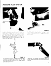
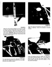
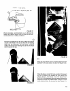
FIGURE 25
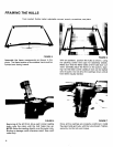
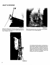
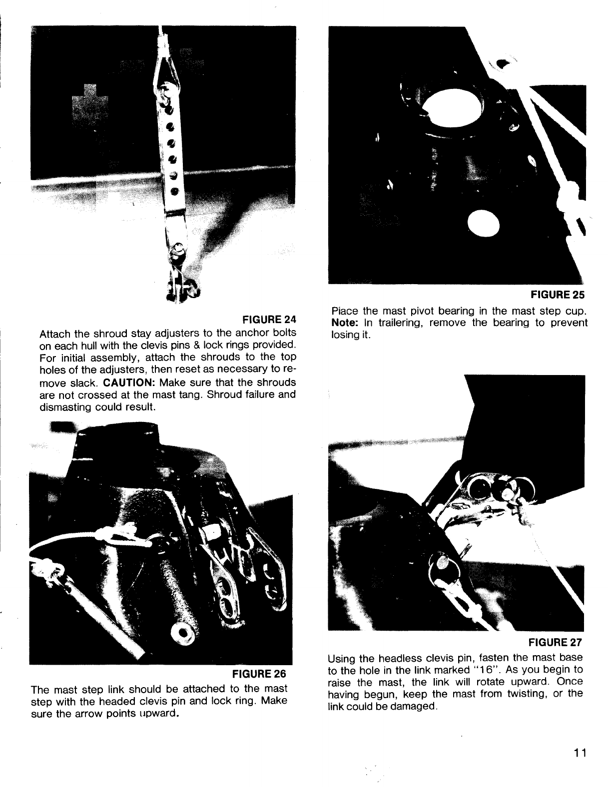
FIGURE 24 Piace the m~st. pivot bearing in the mast step cup.
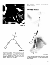
I Attach the shr.oud stay a.dju~ters to th~ anchor bolts ~~~~ i~~ trallerlng, remove the bearing to prevent
I on each hull with the clevIs pins & lock rings provided.
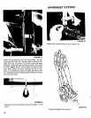
For initial assembly, attach the shrouds to the top
holes of the adjusters, then reset as necessary to re-
move slack. CAUTION: Make sure that the shrouds
are not crossed at the mast tang. Shroud failure and
dismasting could result.
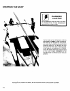
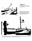
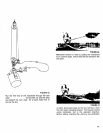
FIGURE 27
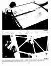
Using the headless clevis pin, fasten the mast base
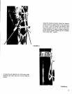
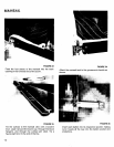
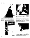
FIGURE 26 to the hole in the link marked "16". As you begin to
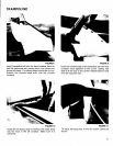
The mast step link should be attached to the mast raise the mast, the link will rotate upward. Once
step with the headed clevis pin and lock ring. Make ~aving begun, keep the mast from twisting, or the
sure the arrow points upward. link could be damaged.
11


