6
2
PANEL DESCRIPTION
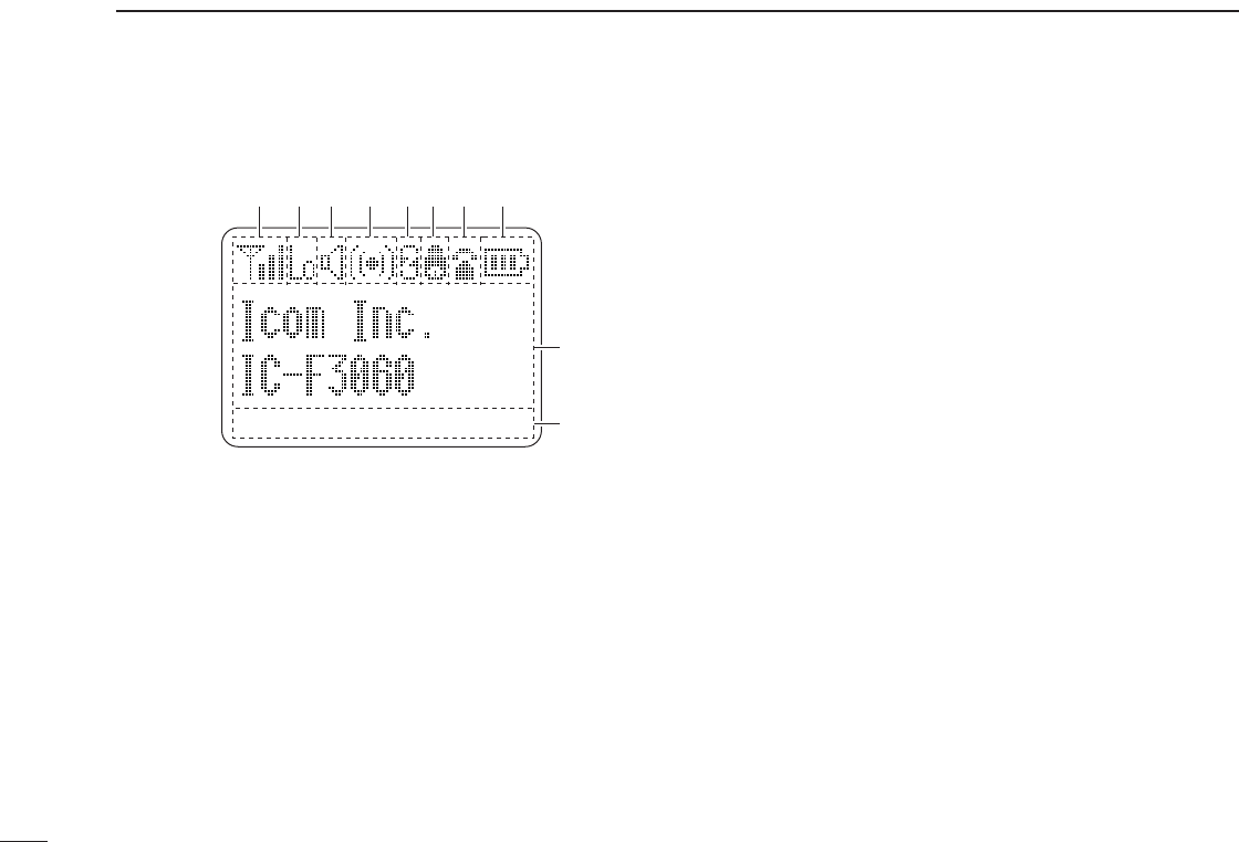
■ Function display
q SIGNAL STRENGTH INDICATOR
Indicates relative signal strength level.
w LOW POWER INDICATOR
Appears when low output power is selected.
e AUDIBLE INDICATOR
➥ Appears when the channel is in the ‘audible’ (un-mute)
condition.
➥ Appears when the specified 2-tone is received.
r COMPANDER INDICATOR
Appears when the compander function is activated.
t SCRAMBLER INDICATOR
Appears when the voice scrambler function is activated.
y BELL INDICATOR
Appears/blinks when the specific 2-tone/DTMF select call
is received, according to the pre-programming.
u CALL CODE MEMORY INDICATOR
Appears when the call code memory is selected.
i BATTERY INDICATOR
Appears or blinks when the battery power decreases to a
specified level.
o ALPHANUMERIC DISPLAY
➥ Displays an operating channel number, channel name,
Set mode contents, DTMF code, etc.
➥ The indication mode can be selected from 1 line or 2
lines. Ask your dealer for details.
• In this instruction manual, the LCD illustration is described
using the 2 lines indication mode.
!0 KEY INDICATOR
Indicate the programmed function of the front panel keys
([P0], [P1], [P2] and [P3]).
SET
CALA TXCU
TXC
q t iuyrew
o
!0


