


4 - 1
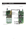
SECTION 4 CIRCUIT DESCRIPTION
Mixer
16
Limiter
AMP
450 kHz 2nd IF filters
30.6 MHz 2nd LO signal
IC231 TA31136FN
1st IF signal
from the IF amplifier (Q211)
11109
87
5
AF "DET" signal
to the AF circuits
"SQCON" signal
from the D/A converter (IC251)
15.3 MHz
Q221
2
2
1
Active
filter
Noise
detector
FM
detector
14
"NOISV" signal to the CPU (IC661, pin 32)
PLL
IC
(IC1)
R5V
×2
X1
Noise
AMP
Noise
comparator
X231
FI231
W/N
SW
W/N
SW
3
FI232
D231
D232
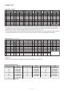
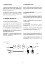
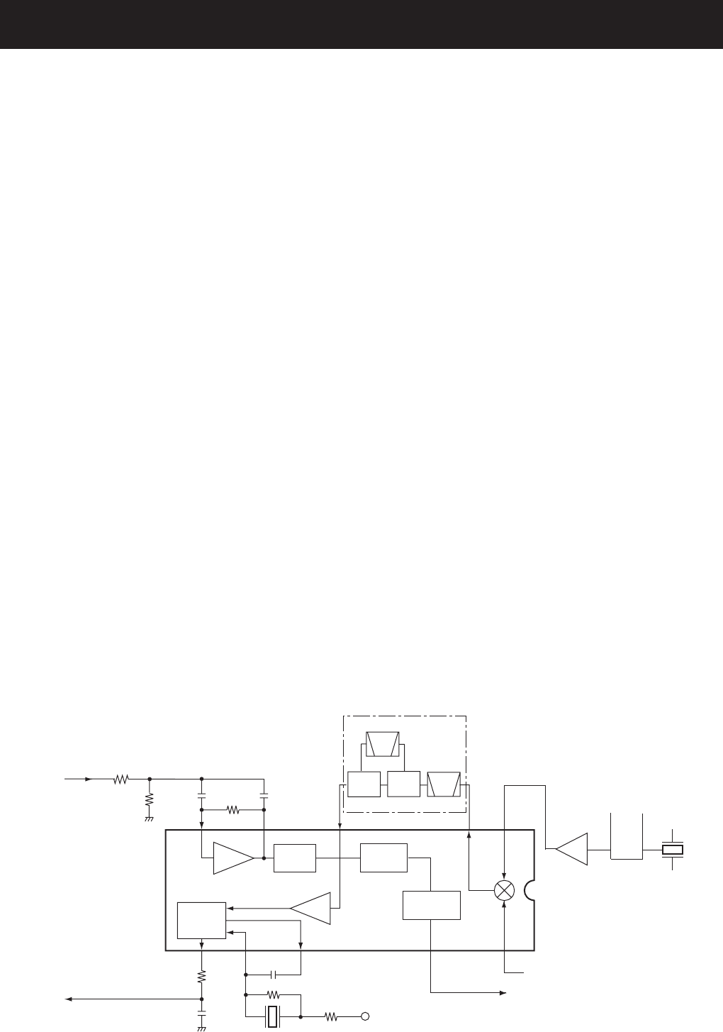
• 2nd IF AND DEMODULATER CIRCUITS
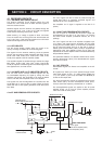
4-1 RECEIVER CIRCUITS
4-1-1 ANTENNA SWITCHING CIRCUIT
The antenna switching circuit toggles receive line and
transmit line. This circuit does not allow transmit signals to
enter the receiver circuits.
Received signals from the antenna are passed through the
low-pass filter (LPF: L131, L132, C131–C136) and applied
to the antenna switching circuit (D151, D152).
While receiving, no voltage is applied to D151 and D152.
Thus, the receive line and the ground are disconnected and
L151, L152, C151, C152 and C153 function as an LPF which
leads received signals to the RF circuits.
4-1-2 RF CIRCUITS
The RF circuits amplify signals within the range of fre-
quency coverage and filters off out-of-band signals.
The signals from the antenna switching circuit are passed
through the two-stage tunable bandpass filter (BPF: D154,
D155, L154–L156, C156, C157, C159–C161, C163, C164,
C168), then applied to the RF amplifier (Q165).
The amplified signals are passed through another two-stage
BPF (D181, D182, L166, L181 C181, C182, C184–C186,
C188) to suppress unwanted signals. The filtered signals are
then applied to the 1st mixer circuit.
4-1-3 1st MIXER AND 1st IF AMPLIFIER CIRCUITS
The 1st mixer circuit converts received signals into the
1st intermediate frequency (IF) signal by mixing with local
oscillator (LO) signal. The converted 1st IF signal is filtered
at the 1st IF filter, then amplified at the 1st IF amplifier.
The signals from the two-stage BPF are converted into the
31.05 MHz 1st IF signal at the 1st mixer (Q191) by being
mixed with the 1st LO signals generated at RX VCO (Q41,
D31–D34).
The 1st IF signal from the 1st mixer is passed through the
crystal filter (FI211) to suppress unwanted signals, and
amplified at the 1st IF amplifier (Q211).
The amplified 1st IF signal is applied to the FM IF IC
(IC231).
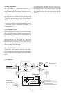
4-1-4 2nd IF AND DEMODULATOR CIRCUITS
The 1st IF signal is converted into the 2nd IF signal and
de-modulated by the FM IF IC. The FM IF IC contains
2nd mixer, limiter amplifier, quadrature detector, etc. in its
package.
The 1st IF signal from the 1st IF amplifier is applied to pin
16 of IC231, and mixed with the 30.6 MHz 2nd LO signal
coming from the doubler (Q221), to convert into the 450 kHz
2nd IF signal and output from pin 3. The 2nd IF signal is
filtered by the ceramic filters (FI231, FI232) to suppress the
heterodyne noise, then applied to IC231 (pin 5) again and
amplified at the limiter amplifier section and demodulated by
the quadrature detector.
The quadrature detector is a detection method which uses a
ceramic discriminator (X231). The demodulated AF signals
are output from pin 9.
4-1-5 AF CIRCUITS
Demodulated signals are filtered and amplified at the AF
circuits.
AF signals from IC231 (pin 9) are passed through the AF
mute switch (IC281 A; pins 1, 2), analog switch (IC282; pins
1, 7), LPF (IC261 C; pins 8–10) and R801 (VR BOARD) to
control the AF output level.
The level controlled AF signals are passed through the AF
mute switch (Q411) and the de-emphasis circuit (R411,
C413) to obtain the frequency characteristic of –6 dB/oct.
The de-emphasized signals are applied to the AF power
amplifier (IC421, pin 4). The AF power amplifier provides
more than 0.3 W of audio power.