


4 - 4
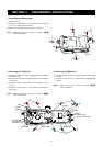
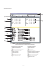
4-5 PORT ALLOCATIONS
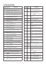
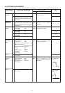
4-5-1 CPU (LOGIC UNIT; IC661)
Pin
number
1
2
3
4
5
6
7
10
11
12
13
17
27
28
29
30
31
32
33
34
35
36
38
46–48
51–70
75
76
77
78
Port
name
BEEP
VSSTB
EXSTB
DASTB
PLSTB
ERXDI
ETXDO
SDATA
SCLK
ESCK
ESDA
CSIFT
WDECV
WETIN
EXTSV
BATTV
TDETV
NOISV
RSSIV
LOINV
TEMPV
CDECV
ATIS
COM0–
COM2
SEG0–
SEG19
Description
Outputs beep audio signals.
Outputs strobe signals for the scrambler
IC (MAIN unit; IC381, pin 10).
Outputs strobe signals for the
expander IC (MAIN unit; IC341, pin 1).
Outputs strobe signals for the D/A
converter (MAIN unit; IC251, pin 6).
Outputs strobe signals for the PLL IC
(MAIN unit; IC1, pin 11).
Input port for cloning signals.
Outputs cloning signals.
Outputs serial data for PLL, scrambler
ICs, etc.
Outputs serial clock for PLL,
scrambler ICs, etc.
Outputs clock signal for the EEPROM
(IC591, pin 6).
I/O port for EEPROM data signal
(IC591, pin 5).
Outputs CPU clock shift signal.
High : While clock is shifted.
Input port for the WX tone detection.
Input port for the transceiver’s internal
inundation detection.
Input port for the external terminal
connecting detection.
Input port for the battery voltage
detection.
Input port for transmit RF level
detection.
Input port for noise level detection.
Input port for RSSI voltage level
detection.
Input port for VCO lock voltage level
detection.
Input port for the transceiver’s internal
temperature detection.
Input port for CTCSS/DTCS detection.
Outputs ATIS wave form.
Output LCD common signals
Output LCD segment signals.
Output LCD contrast control signals.
Output LCD and key’s back light
dimmer control signal.
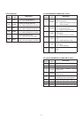
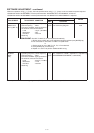
Pin
number
79
80
81
82
83
84
85
86
87
88
89
90
98
99
100
102
103
104
109
110
Description
Outputs scrambler mute signal for the
AF mute circuit (IC481, pin 3).
Low : While scrambler is muting.
Outputs mic mute signal for the AF
mute circuit (IC481, pin 7).
Low : While the microphone is
muting.
Outputs the internal speaker control
signal.
High : While the speaker is muting.
Outputs DTCS’s low-pass filter cut-off
frequency control signal.
Outputs Wide/Narrow control signal.
high : While Narrow is selected.
Outputs the AF mute circuit control
signal.
High : The AF mute circuit is ON.
Outputs AF amplifier’s power supply
control signal.
High : The AF amplifier is ON.
Outputs M5V power supply control
signal.
Low : The common 5V is supplied.
Outputs S5V power supply control
signal.
Low : The common 5V is supplied.
Outputs V5V power supply control
signal.
Low : The common 5V is supplied.
Outputs R5V power supply control
signal.
Low : While receiving.
Outputs T5V power supply control
signal.
Low : While transmitting.
Output DTCS/CTCSS wave form.
Input port for [PTT] swtich detection.
High : While [PTT] switch is pushed.
Input port for HM-138 (optional
speaker-microphone)’s [PTT] swtich
detection.
Low : While HM-138’s [PTT] switch
is pushed.
Input port for the connecting battery
type detection.
Low : While using alkaline cells.
Input port for the [SQL] key.
Low : While [SQL] key is pushed.
Input port for the [UP] key.
Low : While [UP] key is pushed.
CONT1
CONT2
LEDS1
LEDS2
Port
name
STXMS
MICMS
ISPMS
LDTFS
W/NS
AFMS
AFVS
M5VS
S5VS
V5VS
R5VS
T5VS
CENC1
CENC2
CENC3
PTTIN
EPTTIN
BTYPE
SQL
UP