


4 - 1
4-1 RECEIVER CIRCUITS
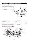
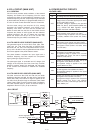
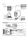
4-1-1 ANTENNA SWITCHING CIRCUIT
(MAIN UNIT)
The antenna switching circuit functions as a low-pass filter
while receiving and as resonator circuit while transmitting.
The circuit does not allow transmit signals to enter receiver
circuits.
Received signals from the antenna connector pass through
the low-pass filter (L131, L132, C131–C136) and antenna
switching circuit (D151, D152). The filtered signals are then
applied to the RF amplifier circuit (Q165).
4-1-2 RF AND 1ST MIXER CIRCUITS (MAIN UNIT)
The 1st mixer circuit converts the received signals to a
fixed frequency of the 1st IF signal with a PLL output
frequency. By changing the PLL frequency, only the desired
frequency will be passed through a pair of crystal filters at
the next stage of the 1st mixer.
The signals from the antenna switching circuit are passed
through the 2-stage bandpass filters (D154, D155, L154,
L155) and amplified at the RF amplifier (Q165). The
amplified signals are passed through another 2-stage
bandpass filters (D181, D182, L181, L182), and then
applied to the 1st mixer circuit (Q199).
The filtered signals are mixed at the 1st mixer (Q199) with
a 1st LO signal coming from the PLL circuit to produce
a 31.05 MHz 1st IF signal. The 1st IF signal is passed
through a pair of crystal filter (FI211) and is then amplified
at the IF amplifier (Q211).
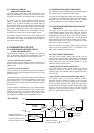
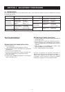
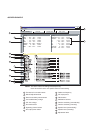
4-1-3 2ND IF AND DEMODULATOR CIRCUITS
(MAIN UNIT)
The 2nd mixer circuit converts the 1st IF signal to a 2nd IF
signal. A double conversion superheterodyne system (which
converts receive signal twice) improves the image rejection
and obtain stable receiver gain.
The 1st IF signal is applied to a 2nd mixer section of the
FM IF IC (IC231, pin 16). The signal is then mixed with a
2nd LO signal for conversion into a 450 kHz 2nd IF signal.
IC231 contains the 2nd mixer, limiter amplifier, quadrature
detector and active filter circuits. A 30.6 MHz 2nd LO
signal is produced at the PLL circuit using the reference
frequency.
The 2nd IF signal from the 2nd mixer (IC231, pin 3)
passes through ceramic filters (FI231, FI232) to remove
unwanted heterodyned frequencies. It is then amplified at
the limiter amplifier section (IC231, pin 5) and applied to
the quadrature detector section (IC231, pins 10 and 11) to
demodulate the 2nd IF signal into AF signals.
4-1-4 AF CIRCUIT (MAIN AND LOGIC UNITS)
AF signals from the FM IF IC (IC231, pin 9) are fed to the
analog switch (IC282).
The AF signals (detected signals) passes through the AF
mute switch (IC281A, pins 2 and 1) via “DET” signal, and
are then applied to the analog switch (IC282, pin 1). The
signals are then applied to the low-pass filter (IC261B,
C266, C267, R270–R272).
The filtered AF signals are applied to and adjusted audio
level at the [VOL] control (VR unit; R801) via the “VOLIN”
signal. The level controlled signals are passed through the
AF mute switch (LOGIC unit; Q411) which is controlled by
“AFMS” signal from the CPU (IC661, pin 84). The passed
signals are applied to the AF power amplifier (IC421, pin
4), and then output to the internal speaker or [EXT SP] jack
after being passed through the de-emphasis circuit (R411,
C413) to obtain the –6 dB/octave frequency characteristics
SECTION 4 CIRCUIT DESCRIPTION
Mixer
16
IF amp.
2nd IF filters
450 kHz
PLL IC
IC1
X1
15.3 MHz
Q221
30.6 MHz
RSSI
IC231 TA31136FN(D)
14
"IF" (1st IF signal: 31.05 MHz)
from RF unit, Q211
"RSSIV" signal to the CPU (pin 33)
11
10
9
87 5
3
2
2
17
16
Active
filter
Noise
detector
FM
detector
Noise
comp.
"NOISV" signal to the CPU (pin 32)
12
C232
C244
R242
C243
C242
C238
C239
"SQCON" signal to the D/A
convertor IC (IC251, pin 2)
"SQLOUT" signal to the D/A
convertor IC (IC251, pin 1)
R240
R241
R239
AF signal "DET"
2nd
R231
X231
450 kHz
R5V
R232
Fl231
Fl232
W/N
SW
Q231
Q232
• 2ND IF AND DEMODULATOR CIRCUITS