


5 - 4
1
2
1
1
2
3
4
1
2
1
2
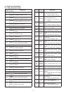
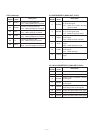
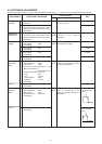
• Operating channel : center frequency
• Receiving
• Operating channel : center frequency
• Connect the RF power meter or 50 Ω
dummy load to the antenna connector.
• Transmitting
• Operating channel : center frequency
• Connect the RF power meter or 50 Ω
dummy load to the antenna connector.
• Transmitting
• Operating channel : center frequency
• [H/L] switch : High
• Transmitting
• [H/L] switch : Mid
• Transmitting
• [H/L] switch : Low
• Transmitting
• [H/L] switch : Extra low
• Transmitting
• Operating channel : center frequency
• Channel spacing : Wide
• [H/L] switch : High
• Connect the audio generator to the
[MIC] jack and set as:
1.0 kHz/200 mV rms.
• Set the FM deviation meter as:
HPF : OFF
LPF : 20 kHz
De-emphasis : OFF
Detector : (P–P)/2
• Transmitting
• Channel spacing : Narrow
• Transmitting
• Operating channel : center frequency
• Channel spacing : Wide
• [H/L] switch : High
• Set the DTCS as : Code 007
• Transmitting
• Channel spacing : Narrow
• Transmitting
PLL LOCK
VOLTAGE
REFERENCE
FREQUENCY
OUTPUT
POWER
FM
DEVIATION
(Wide)
(Narrow)
MODULATION
BALANCE
(Wide)
(Narrow)
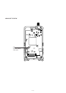
MAIN
Top
panel
Top
panel
Top
panel
Top
panel
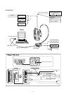
Connect the
digital multimeter to
the check point LV.
Loosely couple the frequency
counter to the antenna
connector.
Connect the RF power meter to
the antenna connector.
Connect the FM deviation
meter to the antenna connector
through the attenuator.
Connect the FM deviation meter
with an oscilloscope to the
antenna connector through the
attenuator.
1.5–3.0 V (Verify)
1.8–3.3 V (Verify)
160.000000 MHz
5.0 W
3.0 W
0.75 W
0.45
±4.15–4.25 kHz
±2.00–2.10 kHz
ADJUSTMENT
ADJUSTMENT CONDITION
MEASUREMENT
VALUE
UNIT
LOCATION
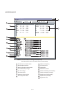
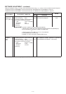
5-2 SOFTWARE ADJUSTMENT
Select an operation using [
↑
] / [
↓
] keys, then set specified value using [
←
] / [
→
] keys on the connected computer keyboard.
Set to flat wave
form
Set to flat wave
form
ADJUSTMENT
ADJUSTMENT CONDITION
UNIT