


Form P6401 Edition 6 11
6. Using a piece of tubing that contacts the inner ring of the
First Stage Intermediate Gear Front Bearing (23), press
the Bearing onto the shaft adjacent to the small spline of
the First Stage Intermediate Gear (21).
7. Using a piece of tubing that contacts the inner ring of the
First Stage Intermediate Gear Rear Bearing (22), press
the Bearing onto the shaft adjacent to the large spline of
the First Stage Intermediate Gear (21).
8. Place the Gear Box Cover Assembly on a workbench
with the output end of the Motor Shaft downward.
9. Position the Bearing nearest the smaller spline on the
shaft of the First Stage Intermediate Gear above the
bearing recess in the Gear Box Cover. Engage the
smaller spline of the Gear with the spline of the Motor
Shaft Gear while pushing the Bearing into the recess.
10. Place the Gear Box Gasket (20) onto the Gear Box Cover
making certain the Gasket fits over the alignment pin in
the Cover and fits well around the large, raised alignment
hub.
11. Position the Gear Box (18) over the assembly and bring
the Gear Box down against the Gasket while making sure
the Bearings enter the bearing recesses in the Gear Box.
Make certain the alignment pin and hub on the Frame
enter the hole and recess in the Gear Box.
12. While keeping the assembly together, turn it over and
insert the eleven Gear Box Cover Cap Screws (41) with
their Lock Washers (42) through the holes of the Cover
into the Gear Box. Tighten the Screws evenly, a little at a
time, using an alternating pattern. Use the Screws to
draw the assembly together without distortion and without
binding.
Motor Assembly
1. The Gear Case Gasket (17) has adhesive on one side of
the Gasket. Place one End Plate (7) flat on a clean
surface with the face having the channel going from the
central opening to the outer edge upward. Orient the
Gasket to the End Plate, making certain the cylinder
dowel hole openings align, and attach it to the End Plate
by bringing the gasket adhesive into contact with the face
of the End Plate. Press it flat onto the face.
2. Slip the End Plate, gasket face trailing, onto the spline
end of the Rotor (12).
3. Install the Front Rotor Bearing Spacer Assembly (14) and
the Front Rotor Bearing (13) onto the splined shaft of the
Rotor and against the End Plate. If the Bearing is a tight
fit on the shaft, use a piece of tubing that contacts the
inner ring of the Bearing and clears the rotor shaft to
press the Bearing onto the shaft.
4. While holding the Rotor in a vertical position, grasp the
spline in copper–covered vise jaws.
5. Place a Vane (10) in each vane slot.
6. Install new Cylinder Seals (8A) in the grooves in the large
hubs of the Cylinder (8).
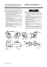
7. For Series 92N Non–reversible Motors, the direction of
rotation of the Motor depends on the relationship of the
Cylinder and End Plates. To obtain desired shaft rotation,
proceed as follows:
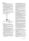
a. Rotate the End Plate until the 17/64” (6.75 mm)
through hole (dowel hole) is facing you. Note there is a
similar hole extending lengthwise through the Cylinder,
and at about 40 to one side of the hole is an air port.
b. Hold the Cylinder upright, facing the dowel hole and
with the air port to the right for clockwise shaft rotation, to
the left for counterclockwise shaft rotation. Then place it
over the Rotor so that the dowel hole in the Cylinder and
End Plate are in alignment. For Series 92R Reversible
Motors, place the Cylinder over the Rotor so that the
dowel hole in the Cylinder and End Plate are in
alignment.
8. The Gear Case Gasket has adhesive on one side of the
Gasket. Place the remaining End Plate flat on a clean
surface with the face having the channel going from the
central opening to the outer edge upward. Orient the
Gasket to the End Plate, making certain the cylinder
dowel hole openings align, and attach it to the End Plate
by bringing the gasket adhesive into contact with the face
of the End Plate. Press it flat onto the face.
9. Install the End Plate, Gasket side trailing, onto the short
hub of the Rotor. Rotate it so that the cylinder dowel hole
is aligned with the corresponding hole in the Cylinder.
Insert the Cylinder Dowel (9) to maintain the alignment
with the Dowel protruding through the Rear End Plate.
10. Slide the Rear Rotor Bearing (5) on the short hub of the
Rotor and against the End Plate. Using snap ring pliers,
install the Rear Rotor Bearing Retainer (6) to keep the
Bearing and End Plate in position.
11. Position the Motor Housing Cover (1) over the Rear Rotor
Bearing and End Plate. Make certain the cylinder dowel
holes and porting are aligned correctly. Remove the
assembly from the vise jaws.
12. Carefully slide the Motor Housing (11) over the
assembled motor and position it against the Motor
Housing Cover.
13. Position the assembled Gear Box (18) against the face of
the Motor Housing. Make certain the spline of the Rotor
engages the teeth of the First Stage Intermediate
Gear(21) properly.
14. Install the Housing Cover Cap Screws (2) along with the
Washers (4). With the motor running at a slow speed
(30 to 40 psig) (267 to 276 kPa) alternately tighten the
Screws to 28 to 31ft–lb. (38.0 to 42.0 Nm) torque.