


Form P6401 Edition 6 3
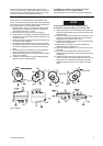
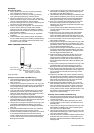
than the Vent plug from the upper side of the motor and
connect an oil line from a gravity feed reservoir. Connect an
overflow line to the Level Plug opening and run it to a pump
to return the lubricant to the gravity feed reservoir.
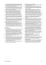
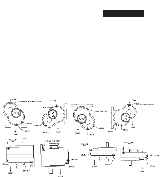
If the Motor is mounted in any position other than
that illustrated, contact an Ingersoll-Rand
Representative for oil level and venting recommendations.
Direction of Shaft Rotation
Series 92N Non–reversible Motors are assembled at the
factory so that the Motor Shaft (36) rotates counterclockwise
when facing the end of the Shaft. When desired, the direction
of the shaft rotation can be changed as follows:
1. Stand the Motor upright on a workbench with the Motor
Housing Cover (1) upward and secure it in position by
clamping the base with a C–clamp.
2. Remove the four Housing Cover Cap Screws (2).
3. Being careful not to damage the Cylinder Seals (8A), pull
the Motor Housing Cover and the Motor Housing (11) off
the Gear Box (18).
4. Grasp the Cylinder (8) with both hands and carefully work
the motor from the Gear Box.
5. While holding the Cylinder with one hand, drive against
the splined end of the Rotor (12) with a soft hammer until
the Front Rotor Bearing (13) comes free from the rotor
shaft.
6. Withdraw the Front Rotor Bearing, Front Rotor Bearing
Spacer Assembly (14) and Front End Plate (7).
7. Withdraw the Cylinder (8), turn it end–for–end, and slide
it back over the Rotor.
8. Install the Front End Plate, Front Rotor Bearing Spacer
Assembly and Front Rotor Bearing.
NOTICE
Press against the inner ring of the Bearing when
pressing the Front Rotor Bearing on the rotor shaft.
9. Align the dowel hole in both End Plates and Cylinder, and
insert the Cylinder Dowel (9) so that it protrudes from the
Rear End Plate.
10. Place the Housing Cover Gasket (4) in the recess in the
Housing Cover so that the dowel notch in the Gasket is
aligned with the dowel hole in the Cover.
11. Set the motor assembly in the Cover so that the Cylinder
Dowel enters the dowel hole.
12. Slide the Motor Housing (11) over the Cylinder and
against the Motor Housing Cover.
13. Place the Gear Box Gasket (17) on the face of the Front
End Plate.
14. Pick up the entire assembly and being careful not to
damage the Cylinder Seals, work it into the pilot recess in
the gear box.
15. Install the Housing Cover Cap Screws and, with the
Motor running at a slow speed using air pressure of 30 to
40 psig (2.07 to 2.76 bar/207 to 276 kPa), alternately
tighten the Screws to 28 to 31 ft–lb. (38.0 to 42.0 Nm)
torque.
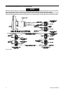
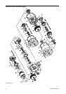
(Dwg. TPB490)