


4 | JL Audio - M600/1 Owner’s Manual
5
POWER CONNECTIONS
Before installing the amplifier, disconnect the
negative (ground) wire from the vessel’s battery.
This will prevent accidental damage to the system,
the vessel and your body during installation.
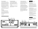
The M600/1’s “+12 VDC” and “Ground”
connections are designed to accept 4 AWG
power wire. 4 AWG is the required wire size for
this amplifier.
If you are installing the M600/1 with other
amplifiers and wish to use a single main power
wire, use 2 AWG or 1/0 AWG main power wire
(depending on the overall current demands of all
the amplifiers in the system). This 2 AWG or
1/0 AWG power wire should terminate into a
fused distribution block mounted as close to
the amplifiers as possible (within 12 inches /
30cm of wire length). The fused output of the
distribution block will connect to the M600/1
with 4 AWG power wire. JL Audio ECS
fused distribution blocks are recommended
(XD-FDBU-2 and XD-FDBU-4)
Note: Smaller AWG numbers mean bigger
wire and vice-versa (1/0 AWG is the largest, 2
AWG is smaller, then 4 AWG, then 8 AWG, etc.).
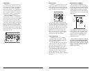
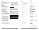
To connect the power wires to the amplifier,
first back out the set screw on the top of the
terminal block, using the supplied 2.5 mm hex
wrench. Strip 1/2 inch (12 mm) of insulation from
the end of each wire and insert the bare wire into
the terminal block, seating it firmly so that no
bare wire is exposed. While holding the wire in
place, tighten the set screw firmly, taking care not
to strip the head of the screw.
The ground connection should be made using
the same gauge wire as the power connection.
Any wires run through barriers must
be protected with a high quality rubber
grommet to prevent damage to the
insulation of the wire. Failure to do so
may result in a dangerous short circuit.
Many vessels employ small (10 AWG - 6 AWG)
wire to connect the alternator’s positive
connection to the battery. To prevent voltage
drops, this wire should be upgraded to 4 AWG
when installing amplifier systems with main
fuse ratings above 60A.
It is common for the alternator to be grounded
through its chassis. If the alternator is not
grounded through its chassis and instead employs
a small (10 AWG - 6 AWG) wire to connect to
ground, this wire should also be upgraded to 4
AWG when installing amplifier systems with main
fuse ratings above 60A.
FUSE REQUIREMENTS
It is absolutely vital that the main power
wire(s) to the amplifier(s) in the system be
fused within 18 inches (45 cm) of the positive
battery post connection. The fuse value at each
power wire should be high enough for all of the
equipment being run from that power wire. If
only the M600/1 is being run from that power
wire, we recommend a 50A fuse be used.
If fusing the amplifier near its power
connections (when more than one amp is being
run from the main power wire), use a 50A fuse.
MAXI™ (big plastic-body) fuses
are recommended.
PRODUCT DESCRIPTION
The M600/1 is a monoblock amplifier utilizing
JL Audio NexD™ high speed switching technology
to deliver outstanding fidelity and efficiency.
The M600/1 can be operated with a wide
variety of source units and system configurations.
Its frequency response is limited to the range
below 500 Hz. It is not designed for driving
midrange speakers or tweeters. Every aspect of its
operation has been optimized for low-frequency
amplification. For detailed specifications, please
refer to Appendix C (page 13).
TYPICAL INSTALLATION SEQUENCE
The following represents the sequence
for a typical amplifier installation, using
an aftermarket source unit. Additional
steps and different procedures may be
required in some applications. If you
have any questions, please contact your
authorized JL Audio dealer for assistance.
1) Disconnect the negative battery post
connection and secure the disconnected cable
to prevent accidental re-connection during
installation. This step is not optional.
2) Run 4 AWG power wire from the battery
location to the amplifier mounting location,
taking care to route it in such a way that it
will not be damaged and will not interfere
with vessel operation. Use 4 AWG or larger
power wire and a power distribution block if
additional amplifiers are being installed with
the M600/1.
3) Connect power wire to the positive battery
post. Fuse the wire with an appropriate fuse
block (and connectors) within 18 inches (45
cm) wire length of the positive battery post.
This fuse is essential to protect the vessel. Do
not install the fuse until the power wire has
been securely connected to the amplifier.
4) Connect negative power wire to the negative
battery post. Use the same size power
wire as the wire connected to the “+12V”
connection (minimum 4 AWG).
5) Run signal cables and remote turn-on wire
from the source unit to the amplifier
mounting location.
6) Run speaker cable from the subwoofer
system(s) to the amplifier mounting
location.
7) Securely mount the amplifier.
8) Connect the positive and negative power
wires to the amplifier. A fuse near the
amplifier is not necessary if the M600/6 is the
only device being run from the fused main
power wire. If the fused main power wire is
shared by the M600/6 and other amplifiers
or devices, fuse each amplifier/device
within 12 inches (30 cm) of wire length,
via a fused distribution block or multiple
individual fuse blocks/on-board fuses.
9) Connect the remote turn-on wire
to the amplifier.
10) Connect the input cables to the amplifier.
11) Connect the speaker cables to the amplifier.
12) Carefully review the amplifier’s control
settings to make sure that they are set
according to the needs of the system.
13) Install the power wire fuse (50A for a
single M600/1) and reconnect the negative
battery post terminal. Install the fuse (50A)
near the amplifier (if applicable).
14) Turn on the source unit at a low level
to double-check that the amplifier is
configured correctly. Resist the temptation
to crank it up until you have verified the
control settings.
15) Make necessary adjustments to the input
sensitivity controls to obtain the right
overall output and the desired balance
in the system. See Appendix A (page 14)
for the recommended input sensitivity
setting method.
16) Enjoy the fruits of your labor with your
favorite music.