


6 | JL Audio - M600/1 Owner’s Manual
7
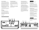
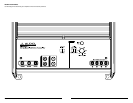
INPUT SECTION
The M600/1’s input section allows you to send
signal to the amplifier section through the use
of two differential-balanced inputs, one for the
left channel signal and one for the right channel
signal. Connection is via RCA-type jacks.
You may run a stereo or a mono signal into
the inputs of the amplifier. The amplifier’s input
section automatically sums stereo signals to mono
for the internal amplifier section. The amplifier
will operate with only one input connection (left
or right), but will require an increase in input
sensitivity to overcome the loss of signal. If a
mono input signal is to be run, we recommend
that you use a “Y-adaptor” to split the mono
signal into both inputs of the amplifier.
Input Voltage Range:
The M600/1’s input section is designed to
accept signal voltages from 100mV – 4V. This
will accommodate all preamp level signals and
many speaker level signals.
To use speaker-level sources, simply splice the
speaker output wires of the source unit onto a
pair of RCA plugs for each input pair. (or use
JL Audio part XD-CLRAIC2-SW) No “line
output converter” is needed in most cases.
If you find that the output cannot be reduced
sufficiently with a direct speaker level signal
applied to the amplifier, you may use a “line
output converter” or voltage divider to reduce the
signal level.
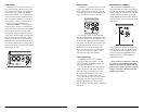
INPUT SENSITIVITY CONTROLS
The control labeled “Input Sens.” can be
used to match the source unit’s output voltage to
the input stage the M600/1 for maximum clean
output. Rotating the control clockwise will result
in higher sensitivity (louder for a given input
voltage). Rotating the control counter-clockwise
will result in lower sensitivity (quieter for a given
input voltage.)
To properly set the amplifier for maximum
clean output, please refer to Appendix A (page
12
) in this manual. After using this procedure,
you can then adjust the “Input Sens.” levels
downward if this is required to achieve the
desired system balance.
Do not increase any “Input Sens.” setting for
any channel(s) of any amplifier in the system
beyond the maximum level established during
the procedure outlined in Appendix A (page 12).
Doing so will result in audible distortion and
possible speaker damage.
TURNON LEAD
The M600/1 uses a conventional +12V remote
turn-on lead, typically controlled by the source
unit's remote turn-on output. The amplifier will
turn on when +12V is present at its “Remote”
input and turn off when +12V is switched off. If
a source unit does not have a dedicated remote
turn-on output, the amplifier’s turn-on lead can
be connected to +12V via a switch that derives
power from an ignition-switched circuit.
The M600/1’s “Remote” turn-on connector is
designed to accept 18 AWG – 12 AWG wire. To
connect the remote turn-on wire to the amplifier,
first back out the set screw on the top of the
terminal block, using the supplied 2.5 mm hex
wrench. Strip 1/2 inch (12mm) of wire and insert
the bare wire into the terminal block, seating it
firmly so that no bare wire is exposed. While
holding the wire in the terminal, tighten the set
screw firmly, taking care not to strip the head of
the screw and making sure that the wire is firmly
gripped by the set screw.