


14 | JL Audio - M600/1 Owner’s Manual
15
“My amplifier shuts off once in a while, usually at higher volumes.”
Check your voltage source and grounding point. The power supply
of the M600/1 will operate with charging system voltages
down to 10V. Shutdown problems at higher volume levels
can occur when the charging system voltage (or remote
turn-on voltage) drops below 10V. These dips can be of
very short duration making them extremely difficult to
detect with a common DC voltmeter. To ensure proper
voltage, inspect all wiring and termination points. It may
also be necessary to upgrade the ground wire connecting
the battery to the vessel’s electrical ground and the power
wire connecting the alternator to the battery. Many
vessels employ small (10 AWG - 6 AWG) wire to ground
the battery and to connect the alternator to the battery.
To prevent voltage drops, these wires should be upgraded
to 4 AWG when installing amplifier systems with main
fuse ratings above 60A. Grounding problems are the
leading cause of misdiagnosed amplifier “failures.”
“My amplifier turns on, but there is no output.”
Check the input signal using an AC voltmeter to measure the
voltage from the source unit while an appropriate low-
frequency test tone is played through the source unit
(disconnect the input cables from the amplifier prior to this
test). 50 Hz is a good choice. A steady, sufficient voltage
(between 0.1 and 4.0-volts) should be present at the output of
the signal cables.
Check the output of the amplifier. Using the procedure explained in
the previous check item (after plugging the input cables back
into the amplifier) test for output at the speaker outputs of
the amplifier. Remove the speaker wires from the amplifier
while doing this to prevent unpleasant noise and possible
speaker damage. Turn the volume up approximately half
way. 5V AC or more should be measured at the speaker
outputs. This output level can vary greatly between
amplifiers but it should not be in the millivolt range with
the source unit at half volume. If you are reading sufficient
voltage, check your speaker connections as explained below.
Check to ensure that the speaker wires are making a good
connection with the metal inside the terminal block. The
speaker wire connectors are designed to accept up to 8 AWG
wire. Make sure to strip the wire to allow for a sufficient
connection with the metal inside the terminal block.
“How do I properly set the input sensitivity on my amplifier?”
Please refer to Appendix A (page 12) to set the input sensitivity for
maximum, low-distortion output.
“My amplifier doesn’t turn on.”
Check the fuse, not just visually, but with a continuity meter. It is
possible for a fuse to have poor internal connections that
cannot be found by visual inspection. It is best to take the
fuse out of the holder for testing. If no problem is found with
the fuse, inspect the fuse-holder.
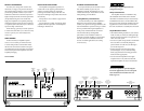
Check the integrity of the connections made to each of the
“+12VDC”, “Ground”, and “Remote” terminals. Ensure
that no wire insulation is pinched by the terminal set screw
and that each connection is tight.
Check to make sure there is +12V at the “Remote” connection of the
amplifier. In some cases, the turn-on lead from the source unit
is insufficient to turn on multiple devices and the use of a relay
is required. To test for this problem, jump the “+12VDC” wire
to the “Remote” terminal to see if the amplifier turns on.
“I hear a repetitive ticking or popping sound coming out of the speaker(s).”
Check the speaker wires for a possible short, either between
the positive and negative leads or between either
speaker lead and the vessel’s electrical ground. If a
short is present, you will experience distorted and/
or attenuated output. The “Status LED” will turn
Amber (yellow) in this situation. It may be helpful to
disconnect the speaker wires from the amplifier and use
a different set of wires connected to a test speaker.
Check the nominal load impedance to verify that each channel
of the amplifier is driving a load equal to or greater than
2 ohms in stereo mode (4 ohms bridged).
“My amplifier’s output fluctuates when I tap on it or hit a bump.”
Check the connections to the amplifier. Make sure that the
insulation for all wires has been stripped back far enough to
allow a good contact area inside the terminal block.
Check the input connectors to ensure that they all are making good
contact with the input jacks on the amplifier.
APPENDIX D: TROUBLESHOOTING