


10 | JL Audio - M600/1 Owner’s Manual
11
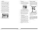
STATUS LED / PROTECTION CIRCUITRY
There is a single multi-color LED on the top
surface of the amplifier to indicate the amplifier’s
operating status.
1) F l a s h i n g G re en : amplifier is powering up,
audio output is muted.
2) Constant Green: amplifier is on and
functioning normally, audio output is active.
3) Constant Red: Indicates that the
amplifier has exceeded its safe operating
temperature, putting the amplifier into a
self-protection mode, which reduces the
peak power output of the amplifier. When its
temperature returns to a safe level, the red
light will return to green and the amplifier will
return to full-power operating mode.
4) Constant Amber (yellow): Indicates
that an over-current condition has occurred and
is accompanied by a muting of the amplifier’s
output. Because the muting behavior may be very
short in duration, it may manifest itself as an
audible, repetitive ticking noise in the output.
Over-current conditions can be caused by a
speaker impedance lower than the optimum load
impedance range for the amplifier or a short-
circuit in the speaker wiring. The latter can result
from a short circuit between the positive and
negative speaker wires or between either speaker
wire and a power wire. The “Status LED” will
remain amber for a few seconds, even if the over-
current condition is of a very short duration.
5) LED off / Amplifier Shuts Off Unexpectedly
The only condition that will shut down
an undamaged M600/6 completely is if battery
voltage or remote turn-on voltage drops below
10 volts. The “Status LED” will turn off when
this occurs. The amplifier will turn back on
when voltage climbs back above 11 volts. If this
is happening in your system, have your charging
system and power wiring inspected.
For more information on troubleshooting this
amplifier, refer to Appendix D (pages 16, 17).
SERVICING YOUR JL AUDIO AMPLIFIER
If your amplifier fails or malfunctions, please
return it to your authorized JL Audio dealer so
that it may be sent in to JL Audio for service.
There are no user serviceable parts or fuses inside
the amplifier. The unique nature of the circuitry
in the JL Audio amplifiers requires specifically
trained service personnel. Do not attempt
to service the amplifier yourself or through
unauthorized repair facilities. This will not only
void the warranty, but may result in the creation
of more problems within the amplifier.
If you have any questions about the installation or
setup of the amplifier not covered in this manual,
please contact your dealer or technical support.
JL Audio Technical Support:
(9 5 4) 4 43 -110 0
9:00 AM – 5:30 PM (Eastern Time Zone)
Monday - Friday
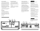
PREOUTS
The M600/1 incorporates a pass-through
preamp output section, so that additional
amplifiers can be easily added to the system.
The preamp output delivers the same signal that
is connected to the M600/1’s inputs.
The preamp output signal by any crossover
filter selected (if the input signal is full-range, the
preamp output will be full-range).
If you plan to use the “Preouts” to feed
a stereo amplifier, you must connect a
stereo signal to the input of the amplifier.
A mono signal into the amplifier will result
in a mono signal out of the preamp output.
SUBWOOFER OUTPUTS
The M600/1 is designed to deliver power into
subwoofer loads equal to or greater than 2 ohms.
The M600/1’s subwoofer outputs are designed
to accept 16 AWG - 8 AWG wire. To connect
the subwoofer wires to the amplifier, first back
out the set screws on the top of the terminal
block, using the supplied 2.5 mm hex wrench.
Strip 1/2 inch (12 mm) of insulation from the
end of each wire and insert the bare wire into
the terminal block, seating it firmly so that no
bare wire is exposed. While holding the wire
in place, tighten the set screw firmly, taking
care not to strip the head of the screw.
You will notice that there are two “+” positive
connections and two “–” negative connections.
This is to facilitate multiple subwoofer wiring.
The two positive and two negative connections
are connected in parallel inside the amplifier
They are not stereo outputs. Connecting two
subwoofers, each to one set of positive and
negative terminals, will result in a parallel
subwoofer connection. If only connecting one
pair of subwoofer wires, it is not necessary to use
both sets of connections.
Subwoofer loads below 2 ohms nominal are not
recommended and may cause the amplifier
to initiate a protection mode which reduces
power output.