


TK-7102H
10
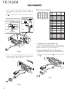
CN2
CN3
A
B
7
8
6
5
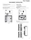
Chassis
Chassis
Cushion
KCT-39
sumi tube
PCB
Face down
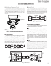
Avoid forming the wiring towards
the shielding cover closure area.
Wire harness
band (Stopper)
End view of this area
9
10
13
15
1
3
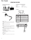
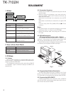
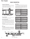
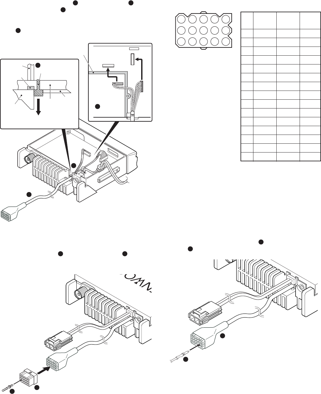
3. Insert the KCT-39 cable (
5
) into the chassis (
6
). The
wire harness band (
7
) must be inside the chassis and
face down.
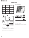
4. Connect the KCT-39 to the TX-RX unit as shown in Figure
5 (
8
).
5. Connect the KCT-39 to the external accessory by inserting
the crimp terminal (
9
) into the square plug (
10
), both of
which are supplied with the KCT-39.
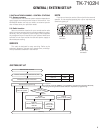
Fig. 5
Fig. 6
1471013
2581114
3691215
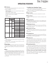
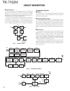
No. Color Internal Name
connector
1 Red CN2-1 SB
2 Pink CN3-1 IGN
3 Black CN2-3 GND
4 Brown CN3-3 DETO
5 Orange CN3-2 DATAI
6 Yellow CN2-8 FNC4
7 Green CN2-7 FNC3
8 Blue CN2-9 FNC5
9 Purple CN2-12 FNC8
10 Gray CN2-10 FNC6
11 White CN2-11 FNC7
12 NC NC
13 NC NC
14
Sky blue
CN2-6 FNC2
15
Turquoise
CN2-5 FNC1
■ Accessory Port Function
REALIGNMENT
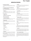
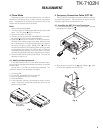
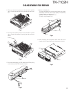
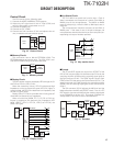
6. Ignition Sense Cable (KCT-18)
The KCT-18 is an optional cable for enabling the ignition
function. The ignition function lets you turn the power to the
transceiver on and off with the car ignition key.
6-2. Connecting the KCT-18 to the Transceiver
1. Install the KCT-39 in the transceiver. (See the KCT-39 sec-
tion)
2. Insert the KCT-18 lead terminal (
1
) into pin 2 of the KCT-
39 (
2
).
Fig. 7
2
1
13
15
1
3