


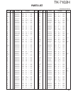
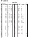
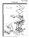
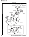
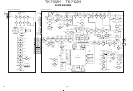
TK-7102H
33
If normal power is not obtained, please follow the
step below
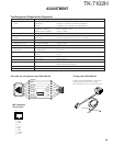
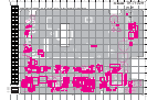
Open the shielding cover (upper), and screw 3 locations
around ANT pin.
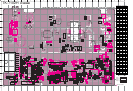
1. Switch off the transceiver.
Impedance of Final FET (Q504) and Drive FET (Q503) can
be measured easily using DVM Ω mode.
Normal condition – Gate : 20kΩ~50kΩ, Drain : 1MΩ~2MΩ
The above impedance values are rough estimations.
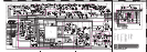
2. Switch on the transceiver. Check the voltage at F501 out-
put point.
The voltage is around 13.6V in receiving condition. The
voltage will be 12.6V~ in transmitting condition. If found
0V at this point then F501 is broken.
3. Remove R516.
4. Connect 50Ω load at the ANT location.
Transmit and check current drain at High power mode.
If the current drain is less than 1A, then Final FET is bro-
ken.
If the current drain is less than 5.0A, short the Drive FET
gate to ground, and check the current drain.
If the current drain is not 0.1A less than the original value,
then the Drive FET is broken.
5. Check input power level at Drive FET gate location.
Connect the wire to [RF] location.
Transmit and check for power to be within the range of
0.3W~0.6W.
If power found is less than 0.3W, check the circuit before
the Drive FET.
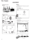
ADJUSTMENT
5. DQT 1) CH : TX low (Wide) Modulation analyzer ANT PC key
Adjust the waveform as below
balance CH : TC center (Wide/Narrow) or Linear detector
CH : TX high (Wide) (LPF : 3kHz)
2) Transmit Oscilloscope
6. MAX 1) CH : TX low (Wide) Modulation analyzer ANT ±4.0kHz (Wide) ±50Hz
balance CH : TC center (Wide/Narrow) or Linear detector MIC ±2.0kHz (Narrow)
CH : TX high (Wide) (LPF : 15kHz) According to the large +, –
2) AG : 1kHz/50mV Oscilloscope
3) Transmit AG
AF V.M
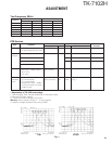
7. MIC 1) CH : TX center (Wide/Narrow) Check ±3kHz±0.2kHz
sensitivity 2) AG : 1kHz/5mV (Wide)
3) Transmit ±1.5kHz±0.1kHz
(Narrow)
8. DQT 1) CH : TX low (Wide) Modulation analyzer ±0.75kHz (Wide) ±0.05kHz
deviation CH : TX center (Wide/Narrow) or Linear detector ±0.35kHz (Narrow)
CH : TX high (Wide) (LPF : 3kHz)
2) Transmit Oscilloscope
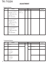
9. QT 1) CH : TX low (Wide) ±0.75kHz (Wide) ±0.05kHz
deviation CH : TX center (Wide/Narrow) ±0.35kHz (Narrow)
CH : TX high (Wide)
2) Transmit
10. DTMF 1) CH : TX center (Wide/Narrow) ±3.0kHz (Wide) ±0.2kHz
/MSK 2) Transmit ±1.5kHz (Narrow)
deviation
Item Condition
Test equipment
Terminal
Parts Method
Specifications/
Remarks
Measurement
Adjustment