


1 RECEPTION
TS-590S CONTENTS 9
Typical built-in RX auxiliary circuits include the variable pass bandwidth circuit, notch filter and noise
blanker (NB). In modern HF transceivers, most of these auxiliary circuits (=auxiliary functions) are
made possible by an arithmetic process of the DSP. As well as the TS-590S, only two auxiliary
circuits operate genuinely at the IF stage: NB and AGC (ATT circuit that functions by receiving the
control signal provided by the DSP).
On the TS-590S, there are two methods available to achieve noise blanking: NB1 and NB2. NB1 is
realized by analog processing and NB2 by digital processing of the IF DSP. Still retaining an analog
noise blanker, TS-590S may seem out of step with the times. But it is critical to have an analog noise
blanker for a receiving system design using narrow roofing filters.
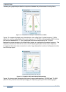
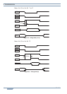
Noise is typically pulse-shaped and when the noise passes a narrow filter, the pulse waveform is
changed to have a wider (longer) pulse width.
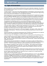
Within the DSP, the processing block of the noise blanker is placed in a stage earlier than the filter
block that determines the final pass bandwidth. Thus, even if the final pass bandwidth is narrowed,
the blanking operation can work properly, free of the influence of the narrowed bandwidth.
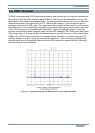
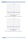
However, roofing filters are located far earlier than the DSP, in the later stage of the first mixer. As a
result, in the event the bandwidth of the roofing filter becomes as narrow as 500 Hz, the pulse width
becomes wider and a conventional digital noise blanker would not deliver a sufficient blanking effect.
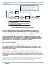
This is the exact case while down conversion is active on the TS-590S and a digital noise blanker
alone may not produce a great enough effect. That is the reason we have placed a filter of pass
bandwidth 6 kHz right after the first mixer. The filter deters the transformation of the pulse shape and
prevents false operation of the noise blanker due to adjacent signals while sending the noise signals
to the analog noise blanker.
During the up conversion, the noise signal is derived from the second IF stage and delivered to the
noise blanker circuit as in previous models.
NB1and NB2 are the name of the functions that have been used in TS-930S and all subsequent
products. NB2 was especially designed to have a blanking effect against noise with a long pulse width
and a long period that has been known as the “Woodpecker.” After the woodpecker noise disappeared,
the NB2 function was not employed, but in recent years a new breed of noise called the “China Dragon”
has appeared. So, there may be cases when NB1 alone may not have a great enough effect on the
China Dragon, NB2 has been spotlighted again. Note, however, NB2 on the TS-590S is realized with
digital processing and, thereafter, totally different from NB2 in the TS-930S era.
As explained above, while the narrow bandwidth of the roofing filter is employed, the noise blanker of
the DSP cannot have a sufficient effect. However, the NB2 realized with the DSP on the TS-590S turns
out to be unexpectedly effective in many occasions, even while the bandwidth is less than 500 Hz in
CW mode. This is because the new NB2 can fully adjust the blanking time to the length of the pulse.
NB2 of the TS-590S is most effective when you want to pick up a weak signal that is almost buried in
the noise with a long pulse width that cannot be eliminated by NB1. Try NB2 in such occasions and
be surprised.
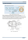
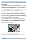
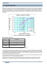
On the TS-590S, by changing the circuitry configuration inside the transceiver, you can change the
sensitivity in the BC band and the attenuation amount of the [ATT] key on the front panel.
1.4 RX Auxiliary Circuits
Hints and Tips “What are NB1 and NB2?”
Hints and Tips “Improvement of sensitivity in the BC band and alteration in ATT attenuation”