


1 RECEPTION
TS-590S CONTENTS 3
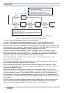
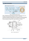
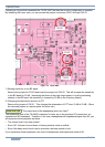
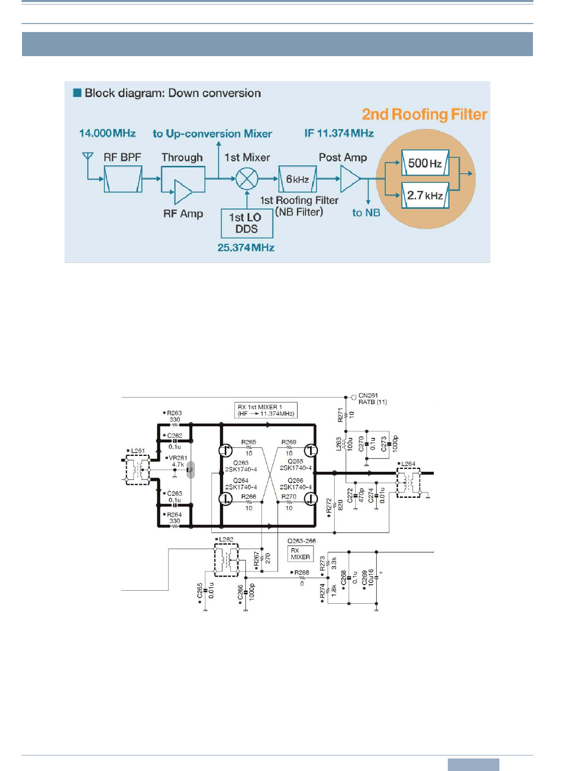
Figure 1-2 Block diagram: Down Conversion
Figure 1-2 describes the circuit configuration around the first mixer of the down-conversion path,
showing the relationships between frequencies upon receipt of a 14 MHz signal.
The signal from the antenna passes the RF BPF or LPF (as a receive LPF, it divides the frequency
band of 30 kHz to 60 MHz into 12 ranges) and RF Amp (or bypasses it) to be sent into the first mixer.
Because in the first mixer section, a different mixer is used for the up conversion and down
conversion respectively, the suitable mixer is selected according to the conditions.
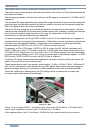
Figure 1-3 Receiver Mixer Circuit
1.2 Down Conversion