


7 STRUCTURAL FEATURES
48 CONTENTS TS-590S
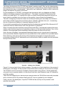
We have also paid much attention to the area and shape of the air inlets/outlets to lessen the
operation noise of cooling fan motors.
To reduce the noise from the air inlets/outlets, the area and shape were examined through repeated
experiments and we have finally succeeded in alleviating the cooling fan motors’ operating noise.
The area of air inlets/outlets of the TS-590S is about 1.5 times larger than that of TS-2000S so that
the suction and emission efficiency is improved.
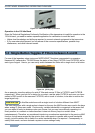
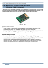
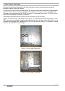
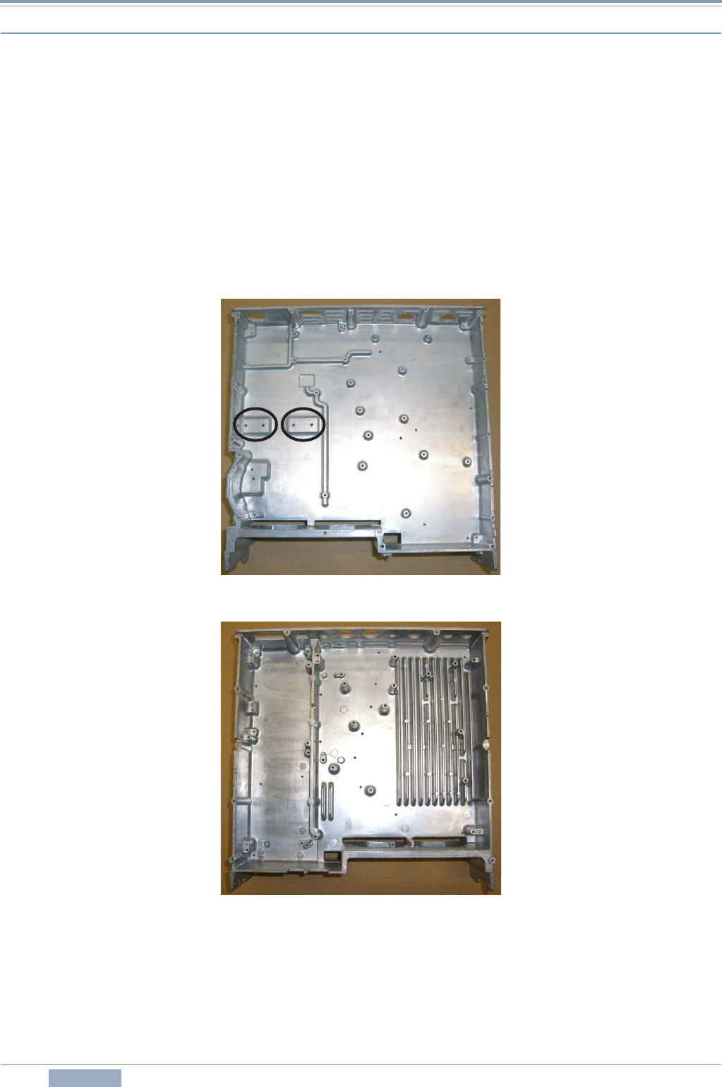
The following figure portrays the aluminum die-cast chassis of the TS-590S.
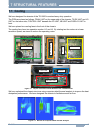
Figure 7-3 shows the side of the FINAL UNIT, Figure 7-4 shows the side of the TX-RX UNIT. Final
FETs are positioned on the two raised areas located to the left on the side of the FINAL UNIT. On the
reverse side of the final FETs, beneath the TX-RX UNIT, a heat sink (Figure 7-5) is placed to remove
heat from the final FETs and discharge it.
Figure 7-3 On the Side of FINAL UNIT
Figure 7-4 On the Side of TX-RX UNIT