


65
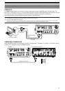
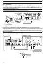
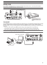
&211(&7,1*3(5,3+(5$/(48,30(17
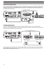
7(50,1$/'(6&5,37,216
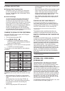
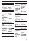
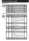
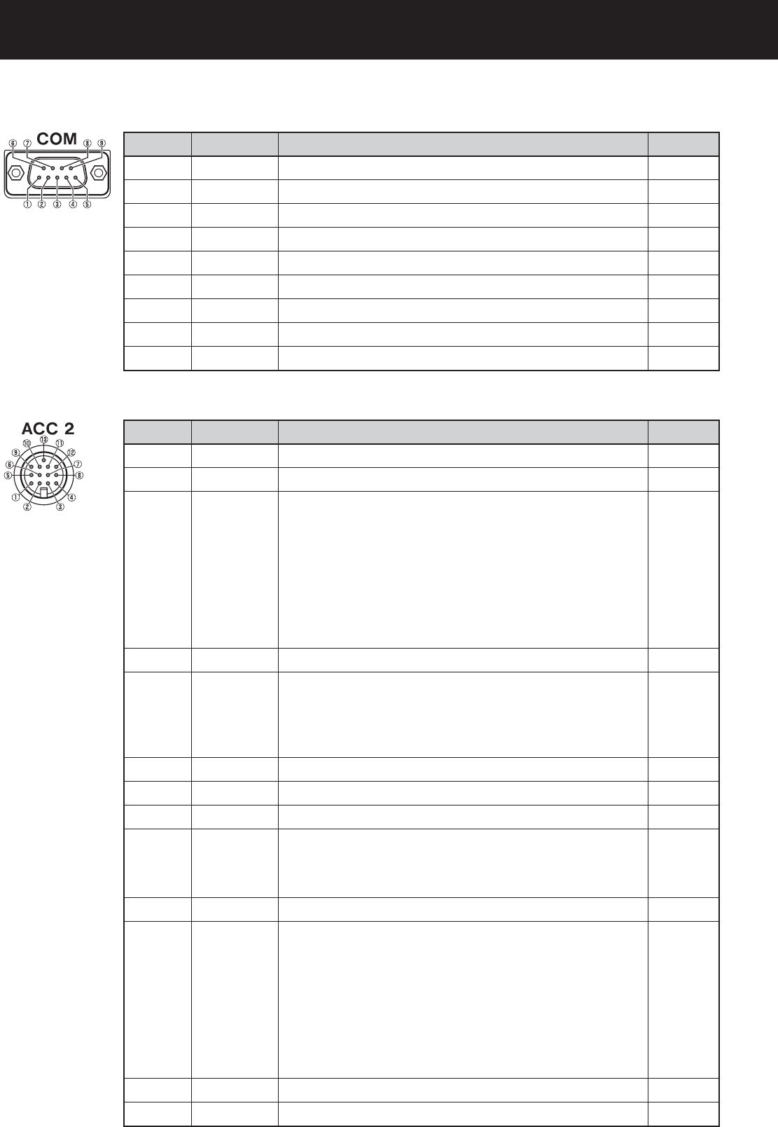
&20&211(&725
Pin No. Pin Name Function I/O
1 NC No connection —
2 RXD
Transmit data
O
3 TXD
Receive data I
4 NC No connection
—
5 GND Ground
—
6 NC No connection —
7 RTS Receive enable I
8 CTS Transmit enable O
9 NC No connection
—
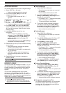
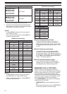
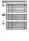
$&&&211(&725
Pin No. Pin Name Function I/O
1 NC No connection
—
2 RTTY
RTTY key input
I
3 ANO
Audio output from the transceiver
• Connect to the audio input of the TNC, MCP, or PC (or PC
interface connection).
• Audio output level is independent from the
AF control setting.
• Audio output level can be changed by adjusting the value
in Menu No. 67. Set the value to a moderate audio output
level. The default value of 4 is approximately 0.5 V
p-p
, which
is a standard modulating signal. The settings of 0 ~ 9 vary
from approximately 0 V
p-p
to 1.2 V
p-p
.
,PSHGDQFH$SSUR[N
O
4 GND Ground
—
5 PSQ
Transceiver squelch control
• Connect to the squelch input of the TNC, MCP, or PC
connection interface.
• Squelch open: Low impedance
• Squelch closed: High impedance
O
6 NC No connection
—
7 NC No connection
—
8 GND Ground
—
9 PKS
PTT input for data communication
• Connect to the PTT output of the TNC, MCP, or PC
connection interface.
• Microphone audio input mutes when transmitting.
I
10 NC No connection
—
11 ANI
Audio input for data communication
• Connect to the audio output of the TNC, MCP, or PC (or PC
interface connection).
• Audio input level is independent from the microphone gain
(set with the [MIC] key).
• Audio input level can be changed by adjusting the value in
Menu No. 66. The default value of 4 is approximately 10
mV
rms
, which is a standard modulating signal. The settings
of 0 ~ 9 vary from approximately 0 mV
rms
to 1 mV
rms
.
,PSHGDQFH$SSUR[N
I
12 GND Ground
—
13 SS PTT input (same as the front panel MIC connector)
I