


68
&211(&7,1*3(5,3+(5$/(48,30(17
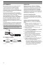
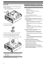
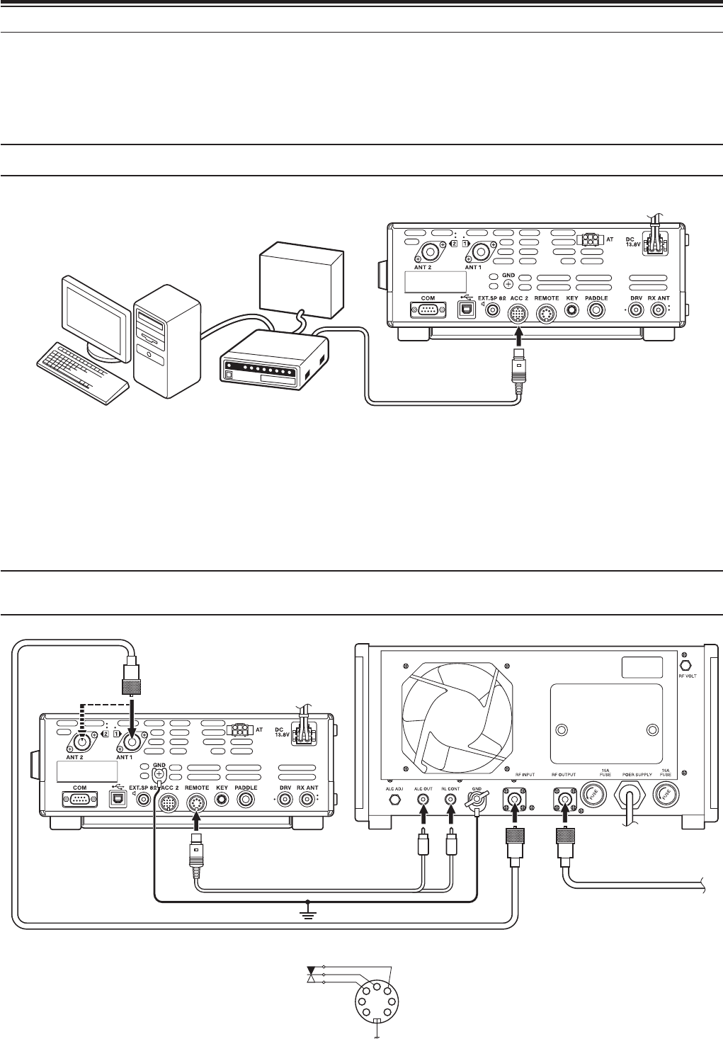
577<23(5$7,21
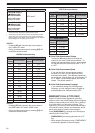
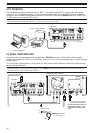
Use the ACC 2 connector to interface with your MCP. If your MCP supports RTTY keying output, connect the
output to pin 2 of the ACC 2 connector. Connect the demodulation input line of the MCP to pin 3 of the ACC 2
connector. Also, connect the transmission control line of the MCP to pin 3 of the REMOTE terminal. Select “FSK”
or “FSR” when you operate the RTTY mode.
Note: Do not share a single power supply between the transceiver and the RTTY equipment. Keep as wide a separation as possible
between the transceiver and the RTTY equipment to reduce noise-pickup by the transceiver.
TS-590S
MCP
Power supply for MCP
Personal computer
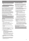
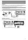
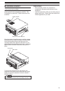
+)0+]/,1($5$03/,),(5
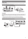
Connect an external transmission power amplifier to the REMOTE connector. Switch ON the linear amplifier
control relay via Menu No. 53 (HF) or 54 (50 MHz). Select “2” or “3” if you use the internal relay to control the linear
amplifier status.
The TX/ RX relay response time is 10 [ms] when you have selected CW Full Break-in and 25 [ms] when you have
selected CW Semi Break-in.
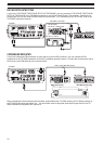
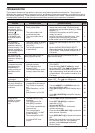
Note: The TX/ RX control method differs, depending on external amplifier models. Some amplifiers enter the TX mode when the control
terminal is grounded. For those amplifiers, connect pin 2 of the REMOTE connector to the GND terminal of the amplifier and connect pin 4
of the connector to the control terminal of the amplifier.
(The TL-922 Linear Amplifier is
a discontinued model. It may
no longer be available in your
area.)
TS-590S
TL-922 (HF linear amplifier)
2
4
1
67
3
5
R
T
Control relay
GND
REMOTE connector
(front view)