


10
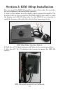
Section 3: RIM 100sp Installation
You can install the RIM 100 module in some other order if you prefer,
but we recommend this installation sequence:
1. Select a flat surface near the display unit to mount the module. The
location must be close enough for the RIM's RS232 data cable to reach
the display unit's RS-232 data cable. Use the RIM 100 as a template to
mark the location of the pilot holes for the four mounting screws.
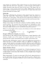
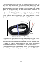
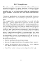
RIM 100sp Radar Interface Module
2. Drill four 1/8" (3 mm) diameter pilot holes in the mounting surface.
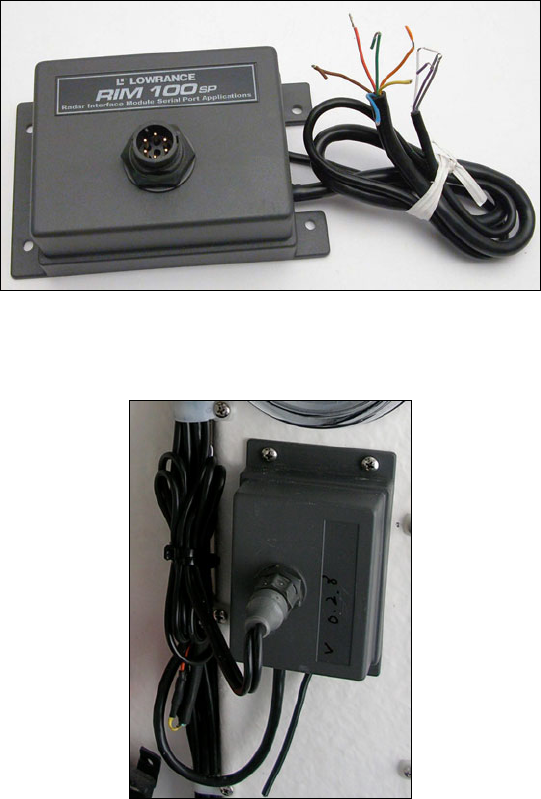
3. Use four 3/4" No. 10 stainless steel screws to mount the RIM 100
module.
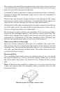
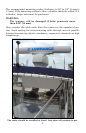
RIM 100 module mounted on a bulkhead.