


11
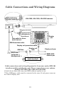
4. Route the radar cable to the RIM 100 location. Connect the RIM 100
radar data cable to the radar antenna power/data output cable using
heat-shrink butt connectors. Follow instructions on the wiring diagram
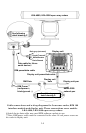
that corresponds to your radar antenna — Detail Drawing A for radome
models or Detail Drawing C for open array models. Diagrams are
shown on pages 11 through 14.
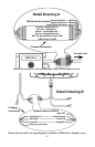
5. Connect the RIM 100 RS-232 data cable to the display unit RS-232
cable using heat-shrink butt connectors. Follow the instructions on the
wiring diagram that corresponds to your radar antenna — Detail
Drawing B for radome models or Detail Drawing D for open array mod-
els.
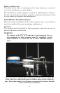
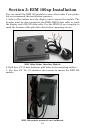
RIM 100 RS-232 Power/Data Cable
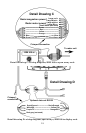
6. The RIM 100's serial device data cable is unused at this time. To pro-
tect the wire ends for future use — and prevent accidental shorts — un-
used wires should be wrapped in electrical tape or capped with wire nuts.
7. Connect the RIM 100 power cable to the same 12-volt power source
as the radar's display unit. The red wire is + and the black wire is –.
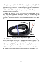
8. After wires have been connected and unused wires insulated, insert
the module's power/data cable plug in the receptacle on the RIM 100.
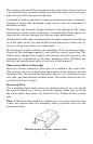
RIM Data
RIM Pw
r